The structure of a High-Density Plasma CVD (HDP-CVD) chamber consists of three primary mechanical sections: a bottom, sidewalls, and a dome. The dome is mounted on top of the sidewalls, and its top dimension defines the effective diameter of the chamber. Functionally, the system relies on a dual-coil configuration, with distinct radio frequency (RF) coils positioned on both the dome and the sidewalls to drive the plasma process.
The performance of an HDP-CVD chamber depends heavily on the geometric relationship between its RF coils. For optimal results, the ratio of the spacing between the top and side coils to the chamber's diameter must be maintained between 0.2 and 0.25.
The Physical Architecture
To understand the HDP-CVD chamber, one must look at how the physical enclosure supports the generation of high-density plasma.
Core Components
The chamber enclosure is built from three distinct parts: the bottom, the sidewalls, and the dome.
The dome sits directly atop the sidewalls, creating a sealed environment necessary for vacuum integrity and gas containment.
Defining Dimensions
The geometry of the chamber is not defined by the bottom or the sidewalls alone.
Instead, the chamber diameter is specifically defined by the top of the dome. This dimension serves as the baseline for calculating critical design ratios.
The Radio Frequency (RF) Configuration
While the physical shell contains the vacuum, the external RF coils are responsible for energy delivery. The HDP-CVD system utilizes a specific two-coil arrangement.
Coil Placement
The chamber features two separate RF coils to shape the plasma density.
A top coil is mounted on the dome structure. Simultaneously, a side coil is positioned along the chamber's sidewalls.
The Critical Geometric Ratio
The vertical distance between these two coils is not arbitrary; it is a vital engineering parameter.
To ensure the system functions correctly, engineers must calculate the ratio of the coil spacing to the chamber diameter.
According to standard design principles for this equipment, this ratio should strictly fall between 0.2 and 0.25.
Critical Design Constraints
Designing or maintaining an HDP-CVD chamber involves strict adherence to geometric precision. Failing to respect the described ratios can compromise the process.
Sensitivity to Coil Spacing
The range of 0.2 to 0.25 is not a guideline but a requirement for optimal performance.
Deviating from this ratio—either by placing coils too close together or too far apart relative to the dome size—likely disrupts the plasma density or uniformity required for the deposition process.
Interaction with Process Gases
While the structure focuses on coil geometry, the chamber must also accommodate the flow of reactant gases.
The enclosure must allow for the introduction of precursors (like silane) and the continuous removal of volatile by-products generated during the film formation.
Optimizing Chamber Design
When evaluating or designing an HDP-CVD system, your focus should shift based on your specific engineering goals.
- If your primary focus is Mechanical Design: Ensure the dome and sidewall integration allows for precise coil mounting that adheres to the established diameter-based ratio.
- If your primary focus is Process Stability: Verify that the ratio of coil spacing to chamber diameter remains consistently between 0.2 and 0.25 to maintain optimal plasma characteristics.
The precise alignment of the dome, sidewalls, and RF coils is the foundational requirement for successful high-density plasma deposition.
Summary Table:
| Component | Description/Function | Key Specification |
|---|---|---|
| Chamber Structure | Composed of bottom, sidewalls, and a dome | Dome defines the chamber diameter |
| RF Coil System | Dual-coil configuration (top coil and side coil) | Shapes and drives plasma density |
| Critical Ratio | Spacing between coils relative to chamber diameter | Optimal range: 0.2 to 0.25 |
| Vacuum Integrity | Sealed environment for gas containment | Supports reactant gas flow and removal |
Elevate Your Thin Film Deposition with KINTEK
Precision is the foundation of high-density plasma processes. At KINTEK, we specialize in providing high-performance laboratory equipment and consumables tailored for advanced semiconductor and materials research. Whether you are optimizing CVD/PECVD systems, utilizing high-temperature furnaces, or managing complex vacuum environments, our expert-engineered solutions ensure process stability and superior results.
From specialized ceramic and quartz components to comprehensive crushing, milling, and thermal systems, KINTEK delivers the reliability your lab demands.
Ready to upgrade your research capabilities? Contact our technical specialists today to find the perfect equipment for your specific application!
Related Products
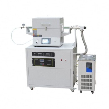
- Chemical Vapor Deposition CVD Equipment System Chamber Slide PECVD Tube Furnace with Liquid Gasifier PECVD Machine
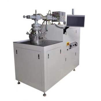
- Customer Made Versatile CVD Tube Furnace Chemical Vapor Deposition Chamber System Equipment
- Multi Heating Zones CVD Tube Furnace Machine Chemical Vapor Deposition Chamber System Equipment
- HFCVD Machine System Equipment for Drawing Die Nano-Diamond Coating
- Split Chamber CVD Tube Furnace with Vacuum Station Chemical Vapor Deposition System Equipment Machine
People Also Ask
- What are the processes of vapor phase deposition? Understand CVD vs. PVD for Superior Thin Films
- How are carbon nanotubes grown? Master Scalable Production with Chemical Vapor Deposition
- What are the advantages of chemical vapor deposition? Achieve Superior Thin Films for Your Lab
- What types of substrates are used in CVD to facilitate graphene films? Optimize Graphene Growth with the Right Catalyst
- How expensive is chemical vapor deposition? Understanding the True Cost of High-Performance Coating