In a standard Plasma-Enhanced Chemical Vapor Deposition (PECVD) system, the configuration relies on a parallel-plate reactor design where the wafers are placed directly onto a grounded aluminum plate. This plate functions as the bottom electrode, while a second, powered electrode is positioned immediately above and parallel to the wafers to facilitate plasma generation.
The system effectively functions as a large capacitor within a vacuum environment. By grounding the bottom wafer holder and applying Radio Frequency (RF) power to the top electrode, the system generates a high-density plasma directly in the narrow gap between the plates, ensuring efficient deposition.
The Parallel-Plate Architecture
The Bottom Electrode (The Grounded Plate)
The foundation of the configuration is an aluminum plate that serves two critical roles simultaneously.
First, it acts as the physical substrate holder, securing the wafers in place during the process.
Second, it acts as the grounded bottom electrode. By grounding the substrate holder, the system ensures that the electric field creates a potential drop across the gap, directing the plasma activity toward the wafer surface.
The Top Electrode (The Powered Source)
Positioned in close proximity to the wafers is the upper electrode.
This component is connected to the RF power supply (typically operating at 13.56 MHz).
When power is applied, this electrode ionizes the reactive gases introduced into the chamber, transforming them into the plasma required for deposition.
The Inter-Electrode Gap
The distance between the top and bottom electrodes is a critical variable.
The second electrode is positioned in close proximity to the wafers to confine the plasma.
This tight spacing ensures high deposition rates and helps maintain plasma density directly over the substrate surface.
Essential Integrated Subsystems
Gas Delivery Integration
While the primary reference focuses on the plates, the top electrode is rarely a solid block.
In most parallel-plate configurations, the top electrode functions as a gas showerhead.
This allows precursor gases to be distributed evenly through the electrode itself, entering the plasma zone directly above the wafers for maximum uniformity.
Thermal Control Mechanisms
The bottom aluminum plate is equipped with a substrate heating device.
This heater raises the wafer to the required process temperature, which is essential for driving the chemical reaction and removing impurities like water vapor to improve film adhesion.
Simultaneously, a water cooling system is often integrated to regulate the temperature of the RF supply and pumps, preventing overheating of the system components.
Understanding the Trade-offs
Proximity vs. Uniformity
The "close proximity" of the electrodes creates a high-density plasma, which is excellent for deposition speed.
However, this configuration creates a sensitivity to mechanical alignment.
If the top and bottom plates are not perfectly parallel, the electrical field will be non-uniform, leading to uneven film thickness across the wafer.
Thermal Lag
Because the wafers sit on a heated plate rather than being heated directly by lamps (in some other designs), there is a reliance on thermal transfer.
Thicker wafers or imperfect contact with the aluminum plate can lead to temperature variations, affecting the consistency of the deposited film.
Optimizing the Configuration for Process Goals
When evaluating or operating a PECVD system, consider how the electrode configuration aligns with your specific constraints.
- If your primary focus is Film Uniformity: Ensure the top electrode (showerhead) design provides even gas flow and that the plates are mechanically leveled to a high tolerance.
- If your primary focus is Deposition Rate: Minimize the gap between the electrodes to increase plasma density, but monitor for potential arcing.
- If your primary focus is Adhesion: Verify that the bottom electrode heater is calibrated to maintain the substrate at the optimal temperature to drive off moisture before deposition begins.
The precise alignment and thermal control of these two parallel plates define the quality and consistency of your final thin film.
Summary Table:
| Component | Role | Material/Specification |
|---|---|---|
| Bottom Electrode | Substrate holder & grounded plate | Aluminum with integrated heater |
| Top Electrode | RF powered source & gas showerhead | Connected to 13.56 MHz RF supply |
| Plasma Zone | Area between electrodes | High-density plasma for deposition |
| Thermal System | Temperature regulation | Substrate heater & water cooling loop |
| Substrate Placement | Direct contact | Wafers sit on the grounded aluminum plate |
Precision thin-film deposition starts with the right PECVD architecture. KINTEK specializes in advanced laboratory solutions, including high-performance CVD and PECVD systems, muffle furnaces, and high-pressure reactors designed for rigorous research environments. Whether you are optimizing battery research with our specialized consumables or scaling semiconductor processes with our precision crushing, milling, and hydraulic press equipment, our team is here to support your technical goals. Contact KINTEK today to discover how our high-temperature systems and laboratory essentials can enhance your process uniformity and efficiency!
Related Products
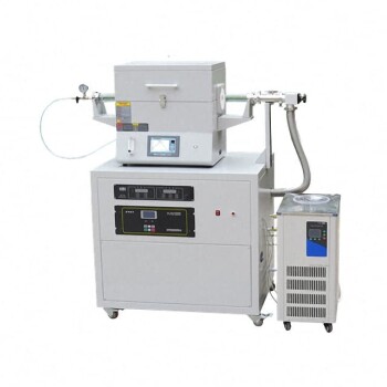
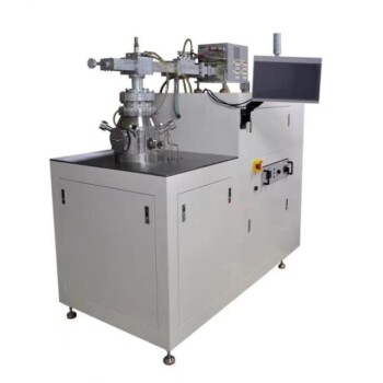
- RF PECVD System Radio Frequency Plasma-Enhanced Chemical Vapor Deposition RF PECVD
- Chemical Vapor Deposition CVD Equipment System Chamber Slide PECVD Tube Furnace with Liquid Gasifier PECVD Machine
- Inclined Rotary Plasma Enhanced Chemical Vapor Deposition PECVD Equipment Tube Furnace Machine
- Inclined Rotary Plasma Enhanced Chemical Vapor Deposition PECVD Equipment Tube Furnace Machine
- 915MHz MPCVD Diamond Machine Microwave Plasma Chemical Vapor Deposition System Reactor
People Also Ask
- Why is a Matching Network Indispensable in RF-PECVD for Siloxane Films? Ensure Stable Plasma and Uniform Deposition
- What is plasma chemical vapor deposition? A Low-Temperature Thin Film Coating Solution
- What is plasma CVD? Unlock Low-Temperature Thin Film Deposition for Sensitive Materials
- What is plasma enhanced chemical vapour deposition process? Unlock Low-Temperature, High-Quality Thin Films
- What is plasma enhanced chemical Vapour deposition process used for fabrication of? A Guide to Low-Temperature Thin Films