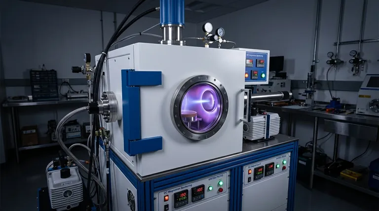
At its core, DC magnetron sputtering is a physical vapor deposition (PVD) technique that uses a magnetically confined plasma to eject atoms from a source material and deposit them as a thin film onto a substrate. The process involves creating a vacuum, introducing an inert gas like argon, applying a high DC voltage to generate a plasma, and then using that plasma to bombard the material you wish to deposit.
The central innovation of magnetron sputtering is its use of a magnetic field. This field traps electrons near the target surface, dramatically increasing plasma density, which allows for a much faster and more efficient deposition process at lower operating pressures.
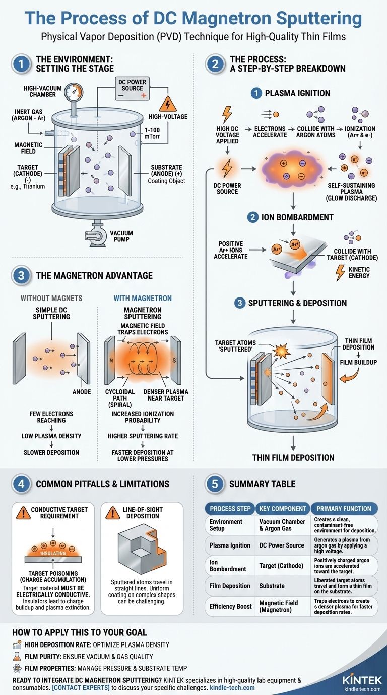
The Environment: Setting the Stage for Deposition
To understand the sputtering process, we must first understand the highly controlled environment in which it occurs. Each component plays a critical role.
The Vacuum Chamber
The entire process takes place inside a high-vacuum chamber. This is essential to remove air and other contaminants that would otherwise react with the sputtered atoms and compromise the purity and quality of the final film.
The Target and Substrate
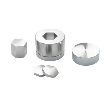
The target is a solid slab of the material you intend to deposit (e.g., titanium, aluminum). It is connected to the negative terminal of a power supply, making it the cathode.
The substrate is the object you want to coat. It is positioned to face the target, ready to receive the deposited atoms.
The Power Source and Inert Gas
A high-voltage DC (Direct Current) power source creates a powerful electric field between the target (negative) and the chamber/anode (positive).
An inert gas, most commonly argon (Ar), is introduced into the vacuum chamber at a very low pressure (typically 1 to 100 mTorr). This gas provides the atoms that will be ionized to create the plasma.
The Sputtering Process: A Step-by-Step Breakdown
Once the environment is prepared, the deposition process can begin. It unfolds in a precise sequence of events driven by physics.
Step 1: Plasma Ignition
A high DC voltage is applied. This powerful electric field accelerates stray electrons within the chamber to high speeds. These energetic electrons collide with neutral argon gas atoms, knocking additional electrons free.
This collision creates a positively charged argon ion (Ar+) and another free electron, which then accelerates and collides with another argon atom. This chain reaction, known as a glow discharge, rapidly creates a self-sustaining plasma—a cloud of positive ions and free electrons.
Step 2: Ion Bombardment
Due to the strong electric field, the positively charged argon ions are accelerated with great force away from the anode and toward the negatively charged target.
They collide with the target surface with significant kinetic energy, acting like a subatomic sandblaster.
Step 3: Sputtering and Deposition
The impact of each argon ion is forceful enough to physically knock out, or "sputter," atoms from the target material.
These liberated target atoms travel through the low-pressure chamber and land on the substrate, gradually building up a dense, high-quality thin film.
The Magnetron Advantage: Why the Magnetic Field is Critical
Simple DC sputtering works, but adding magnets behind the target—creating a "magnetron"—revolutionizes the process's efficiency.
Trapping Electrons for Efficiency
The magnetic field is configured parallel to the target surface. This field traps the highly mobile electrons, forcing them into a spiral, cycloidal path very close to the target.
Without the magnetic field, electrons would quickly fly to the anode, limiting their ability to create plasma.
Creating a Denser Plasma
By trapping electrons near the target, their path length is massively increased. This dramatically raises the probability that they will collide with and ionize neutral argon atoms.
The result is a much denser plasma concentrated directly in front of the target, which is precisely where it is needed most.
The Practical Benefits
A denser plasma means more argon ions are available to bombard the target. This leads directly to a higher sputtering rate, meaning films can be deposited much faster.
Furthermore, this enhanced ionization efficiency allows the process to be sustained at lower gas pressures, improving the quality and purity of the resulting film.
Common Pitfalls and Limitations
While powerful, DC magnetron sputtering is not a universal solution. Understanding its primary limitation is key to its proper application.
The Conductive Target Requirement
The most significant limitation of the DC method is that the target material must be electrically conductive.
If the target is an insulating (dielectric) material, the positive charge from the bombarding argon ions will accumulate on its surface. This buildup, known as "target poisoning," eventually neutralizes the negative bias and extinguishes the plasma, stopping the sputtering process.
Line-of-Sight Deposition
Like other PVD methods, sputtering is a line-of-sight process. The sputtered atoms travel in relatively straight lines, which can make it challenging to uniformly coat complex, three-dimensional shapes without sophisticated substrate manipulation.
How to Apply This to Your Goal
Controlling the process requires understanding how each variable impacts the final outcome.
- If your primary focus is achieving a high deposition rate: Your main lever is increasing plasma density, which is achieved by optimizing the magnetic field strength and the power delivered to the target.
- If your primary focus is ensuring film purity: The quality of the initial vacuum and the purity of the process gas are paramount to prevent unwanted atoms from being incorporated into the film.
- If your primary focus is controlling film properties: Factors like gas pressure and substrate temperature must be precisely managed, as they influence the energy of the depositing atoms and the resulting film's microstructure.
Ultimately, understanding these fundamental mechanics empowers you to control and optimize the creation of high-quality thin films for your specific application.
Summary Table:
| Process Step | Key Component | Primary Function |
|---|---|---|
| Environment Setup | Vacuum Chamber & Argon Gas | Creates a clean, contaminant-free environment for deposition. |
| Plasma Ignition | DC Power Source | Generates a plasma from argon gas by applying a high voltage. |
| Ion Bombardment | Target (Cathode) | Positively charged argon ions are accelerated toward the target. |
| Film Deposition | Substrate | Liberated target atoms travel and form a thin film on the substrate. |
| Efficiency Boost | Magnetic Field (Magnetron) | Traps electrons to create a denser plasma for faster deposition rates. |
Ready to integrate DC magnetron sputtering into your lab's workflow? KINTEK specializes in high-quality lab equipment and consumables for all your thin film deposition needs. Whether you are researching new materials or scaling up production, our expertise ensures you get the precise, reliable results you demand. Contact our experts today to discuss how we can support your laboratory's specific challenges and goals.
Visual Guide
Related Products
- RF PECVD System Radio Frequency Plasma-Enhanced Chemical Vapor Deposition RF PECVD
- Electron Beam Evaporation Coating Oxygen-Free Copper Crucible and Evaporation Boat
- Inclined Rotary Plasma Enhanced Chemical Vapor Deposition PECVD Equipment Tube Furnace Machine
- Chemical Vapor Deposition CVD Equipment System Chamber Slide PECVD Tube Furnace with Liquid Gasifier PECVD Machine
- Electrolytic Electrochemical Cell for Coating Evaluation
People Also Ask
- Why does PECVD commonly use RF power input? For Precise Low-Temperature Thin Film Deposition
- How does RF power create plasma? Achieve Stable, High-Density Plasma for Your Applications
- What are the applications of PECVD? Essential for Semiconductors, MEMS, and Solar Cells
- What is plasma activated chemical vapour deposition method? A Low-Temperature Solution for Advanced Coatings
- What are the benefits of PECVD? Achieve Superior Low-Temperature Thin Film Deposition