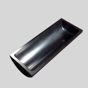
Coating the internal walls of a reaction vessel with titanium dioxide (TiO2) serves a singular, critical function: it transforms the container from a passive holding tank into an active participant in the chemical process. By treating the walls, engineers create a massive, continuous photocatalytic interface. This ensures that the degradation reaction occurs simultaneously across the entire wetted surface area, rather than being limited to specific mixing zones.
The application of a TiO2 coating converts the reactor walls into a reactive surface that generates powerful hydroxyl radicals under UV light, extending the degradation process to every point where the liquid contacts the vessel.
Transforming the Vessel into an Active Interface
Activation Through UV Exposure
The process begins when the internal coating is exposed to ultraviolet (UV) light. This exposure serves as the catalyst, exciting the titanium dioxide layer.
Upon excitation, the coating generates electron-hole pairs. This is the fundamental physical change that allows the solid wall to initiate chemical reactions in the liquid it contains.
Production of Hydroxyl Radicals
Once the electron-hole pairs are generated, they interact immediately with the environment. Specifically, they react with water molecules or hydroxyl ions that are adsorbed (stuck) to the surface of the coating.
This interaction produces hydroxyl radicals. These radicals are highly reactive agents responsible for the breakdown or degradation of target compounds within the fluid.
Maximizing Reaction Efficiency
Utilization of Wetted Surface Area
The primary engineering advantage of this design is the utilization of surface area. In a standard vessel, the walls are inert boundaries.
In a TiO2-coated vessel, the entire wetted surface area becomes a reaction site. This maximizes the contact zone between the photocatalyst and the fluid, ensuring that degradation occurs uniformly wherever the liquid touches the wall.
Understanding the Operational Constraints
Reliance on Light Penetration
While this method creates a large active surface, it is entirely dependent on the delivery of energy. The TiO2 coating acts only when it is successfully excited by UV light.
If the vessel geometry or the fluid's opacity prevents UV light from reaching the coated walls, the generation of electron-hole pairs will cease. The coating is functionally useless without direct and consistent irradiation.
Surface Contact Limitations
The reaction is strictly interfacial. The degradation relies on reactants (water molecules or hydroxyl ions) physically adhering to or contacting the wall.
This means the system's efficiency is dictated by the surface-to-volume ratio. If the vessel is too large, the volume of liquid in the center may not interact sufficiently with the active walls, potentially necessitating agitation or turbulence to ensure all fluid eventually contacts the coating.
Optimizing Photocatalytic System Design
- If your primary focus is maximizing throughput: Ensure your vessel geometry allows UV light to reach every square inch of the internal coating to prevent dead zones.
- If your primary focus is consistent degradation: Design the fluid flow to maximize the turnover rate of liquid against the wetted surface area, ensuring constant contact with the generated hydroxyl radicals.
By integrating the catalyst directly into the reactor structure, you eliminate the need for downstream filtration of catalyst particles while maximizing the reactive surface area.
Summary Table:
| Feature | Function & Impact |
|---|---|
| Activation Source | Ultraviolet (UV) Light exposure |
| Primary Mechanism | Generation of electron-hole pairs on the vessel surface |
| Reactive Species | Highly reactive Hydroxyl Radicals (•OH) |
| Surface Utilization | Entire wetted surface area becomes an active reaction site |
| Operational Benefit | Eliminates the need for downstream catalyst filtration |
| Key Constraint | Dependent on UV light penetration and surface-to-volume ratio |
Maximize Your Photocatalytic Efficiency with KINTEK
Are you looking to optimize your chemical processes with high-performance reaction environments? KINTEK specializes in advanced laboratory equipment, including high-temperature high-pressure reactors and autoclaves, precisely engineered to support specialized coatings and photocatalytic applications.
Our comprehensive range of electrolytic cells, electrodes, and custom reaction vessels ensures that researchers and industrial engineers have the tools needed for uniform degradation and superior throughput. Whether you require precise thermal control or specialized material compatibility, KINTEK provides the reliability and innovation your lab deserves.
Ready to upgrade your reactor design? Contact our technical experts today to find the perfect solution for your research and production needs!
References
- Luis A. González-Burciaga, José B. Proal-Nájera. Statistical Analysis of Methotrexate Degradation by UV-C Photolysis and UV-C/TiO2 Photocatalysis. DOI: 10.3390/ijms24119595
This article is also based on technical information from Kintek Solution Knowledge Base .
Related Products
- Carbon Graphite Boat -Laboratory Tube Furnace with Cover
- Custom PTFE Teflon Parts Manufacturer for Microwave Digestion Tank
- Tungsten Evaporation Boat for Thin Film Deposition
- Engineering Advanced Fine Ceramics Alumina Crucibles (Al2O3) for Thermal Analysis TGA DTA
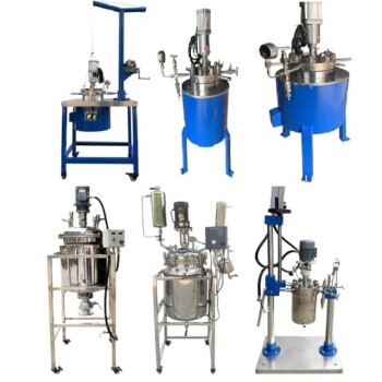
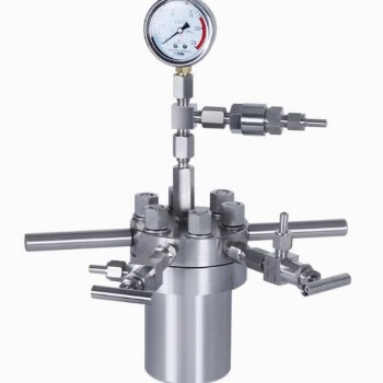
- Stainless High Pressure Autoclave Reactor Laboratory Pressure Reactor
People Also Ask
- What metals can you melt in a graphite crucible? A Guide to Safe & Efficient Melting
- What is the disadvantage of graphite furnace? Managing Reactivity and Contamination Risks
- What is the use of graphite tube? Essential for Extreme Heat & Corrosive Environments
- Why is graphite used in furnaces? For Extreme Heat, Purity, and Efficiency
- What is the temperature range of graphite crucible? Choose the Right Crucible for Your High-Temp Application