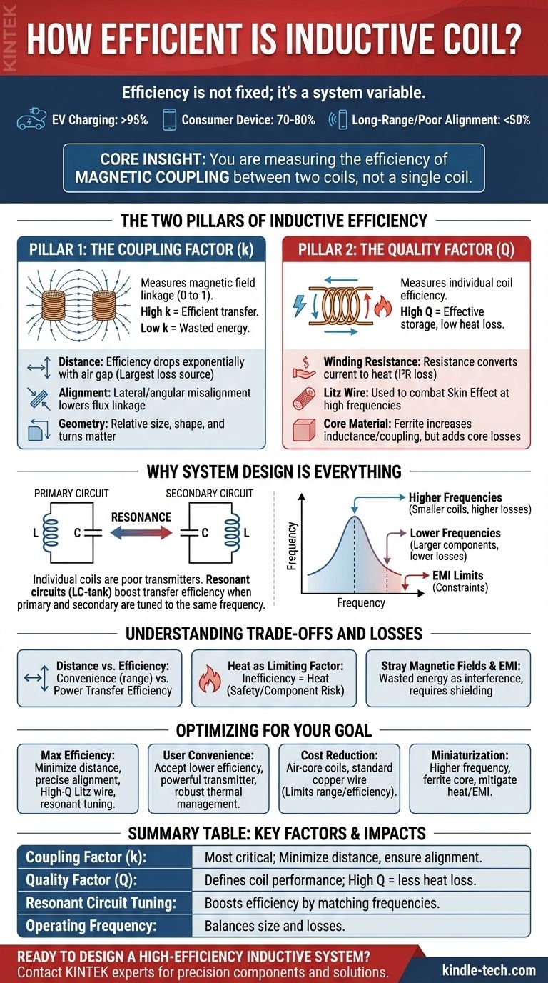
The efficiency of an inductive coil is not a fixed number, but a variable that depends entirely on the system it operates within. While a highly optimized system for electric vehicle charging can achieve over 95% efficiency, a simple consumer device might operate at 70-80%, and a long-range or poorly aligned system could easily drop below 50%. The efficiency is defined by the interaction between the transmitting coil, the receiving coil, and their operating environment.
The core insight is that you are not measuring the efficiency of a single coil, but the efficiency of the magnetic coupling between two coils. This efficiency is primarily dictated by three factors: the distance and alignment between the coils, the intrinsic quality of the coils themselves, and the electrical tuning of the system.
The Two Pillars of Inductive Efficiency
To understand efficiency, you must look at two distinct but related metrics: the coupling factor of the system and the quality factor of the individual coils.
Pillar 1: The Coupling Factor (k)
The coupling factor (k) is the single most important variable for system efficiency. It is a measure (from 0 to 1) of how much of the magnetic field generated by the primary coil successfully passes through, or "links" with, the secondary coil.
A high coupling factor means most of the magnetic energy is being transferred. A low coupling factor means most of the magnetic field is radiating into empty space, representing wasted energy.
Three physical parameters dominate the coupling factor:
- Distance: Efficiency drops exponentially as the air gap between coils increases. This is the most significant source of loss in most wireless power systems.
- Alignment: Any misalignment, whether lateral (off-center) or angular (tilted), reduces the effective area for magnetic flux linkage, drastically lowering the coupling factor.
- Geometry: The relative size, shape, and number of turns of the coils play a critical role. Larger coils can maintain better coupling over slightly larger distances, but have their own trade-offs.
Pillar 2: The Quality Factor (Q)
The Quality Factor (Q) measures a coil's individual efficiency. A high-Q coil is one that stores magnetic energy very effectively while losing very little energy as heat.
The primary enemy of a high Q-factor is resistance. Any electrical resistance in the coil windings converts current into waste heat (I²R loss) instead of building a magnetic field.
Factors affecting Q include:
- Winding Resistance: Using thicker wire reduces basic DC resistance. For high-frequency applications, Litz wire (which consists of many small, individually insulated strands) is used to combat the skin effect, where current crowds to the outer surface of the conductor.
- Core Material: Air-core coils have no core losses but offer lower inductance. Using a ferrite core can dramatically increase inductance and guide the magnetic field, improving the Q-factor and coupling. However, the ferrite itself can introduce new losses (hysteresis and eddy current losses) if not chosen correctly for the operating frequency.
Why System Design is Everything
Even with perfect coils, overall efficiency depends on how they are integrated into a larger electrical circuit.
The Critical Role of Resonance
Individual coils are poor power transmitters. To achieve high efficiency, they are almost always part of a resonant circuit, typically an LC-tank (Inductor-Capacitor).
By adding a capacitor, the circuit is tuned to a specific resonant frequency. When the primary and secondary circuits are tuned to the same frequency, they can exchange energy with minimal loss, dramatically boosting transfer efficiency even with mediocre coupling.
Choosing the Operating Frequency
The choice of frequency is a critical trade-off.
- Higher frequencies allow for smaller, more compact coils but can increase losses due to the skin effect in the windings and core losses in ferrites.
- Lower frequencies reduce these losses but require larger and heavier coils and capacitors to achieve resonance.
- Regulatory limits on electromagnetic interference (EMI) also constrain frequency choices.
Understanding the Trade-offs and Losses
Designing an inductive system is an exercise in managing competing priorities.
The Distance vs. Efficiency Compromise
There is no escaping this fundamental trade-off. A demand for greater distance or positioning freedom (convenience) will always come at the cost of lower power transfer efficiency.
Heat as a Limiting Factor
All inefficiency ultimately manifests as heat. In the primary coil, this is wasted electrical power. In the secondary coil (e.g., inside a sealed smartphone or medical implant), this heat can damage components or pose a safety risk. High-efficiency systems are crucial for managing thermal load.
Stray Magnetic Fields and EMI
A magnetic field that does not link with the secondary coil is wasted energy. This stray field is also a form of electromagnetic interference (EMI) that can disrupt nearby electronics. Shielding can contain these fields but adds cost, weight, and complexity.
Optimizing for Your Specific Goal
Your approach to design or component selection should be driven by your primary objective.
- If your primary focus is maximum power transfer efficiency: Prioritize minimizing the distance and ensuring precise alignment between coils, and use high-Q Litz wire coils in a finely tuned resonant circuit.
- If your primary focus is user convenience (range and freedom): Accept a lower efficiency figure and compensate with a more powerful transmitter and robust thermal management on the receiver.
- If your primary focus is cost reduction: Use simpler air-core coils and standard copper wire, but understand this will severely limit your effective range and overall efficiency.
- If your primary focus is miniaturization: Operate at a higher frequency with a carefully selected ferrite core, paying close attention to mitigating heat and EMI.
By understanding these fundamental principles, you can engineer a system that meets your specific efficiency, cost, and performance targets.
Summary Table:
| Factor | Impact on Efficiency | Key Considerations |
|---|---|---|
| Coupling Factor (k) | Most critical; dictates energy transfer success. | Maximized by minimizing distance, ensuring alignment, and matching coil geometry. |
| Quality Factor (Q) | Defines individual coil performance; higher Q = less energy lost as heat. | Optimized using Litz wire, low-resistance materials, and appropriate core selection. |
| Resonant Circuit Tuning | Dramatically boosts efficiency by matching primary and secondary coil frequencies. | Requires precise capacitor selection to form an efficient LC-tank circuit. |
| Operating Frequency | Balances coil size with losses (skin effect, core losses). | Higher frequencies allow miniaturization but increase potential losses. |
Ready to design a high-efficiency inductive system for your laboratory?
The principles of magnetic coupling and thermal management are critical for reliable lab equipment. At KINTEK, we specialize in providing the components and expertise for precision heating and power transfer applications. Whether you are developing a new instrument or optimizing an existing process, our team can help you select the right materials and design for maximum efficiency and performance.
Let's discuss your project requirements. Contact our experts today to explore how KINTEK's lab equipment solutions can power your innovation.
Visual Guide
Related Products
- Conductive Carbon Cloth Carbon Paper Carbon Felt for Electrodes and Batteries
- Copper Foam
- Laboratory CVD Boron Doped Diamond Materials
People Also Ask
- What is carbon cloth made of? Discover the Versatile High-Performance Fabric
- How should carbon materials be cleaned before use? Ensure Peak Performance with Proper Prep
- How can the electrolyte wettability of carbon cloth be enhanced? Unlock Superior Electrochemical Performance
- What are the material properties of carbon cloth? Harness Strength, Conductivity & Flexibility
- What are the electrode materials? A Guide to Choosing the Right Conductor for Your Application