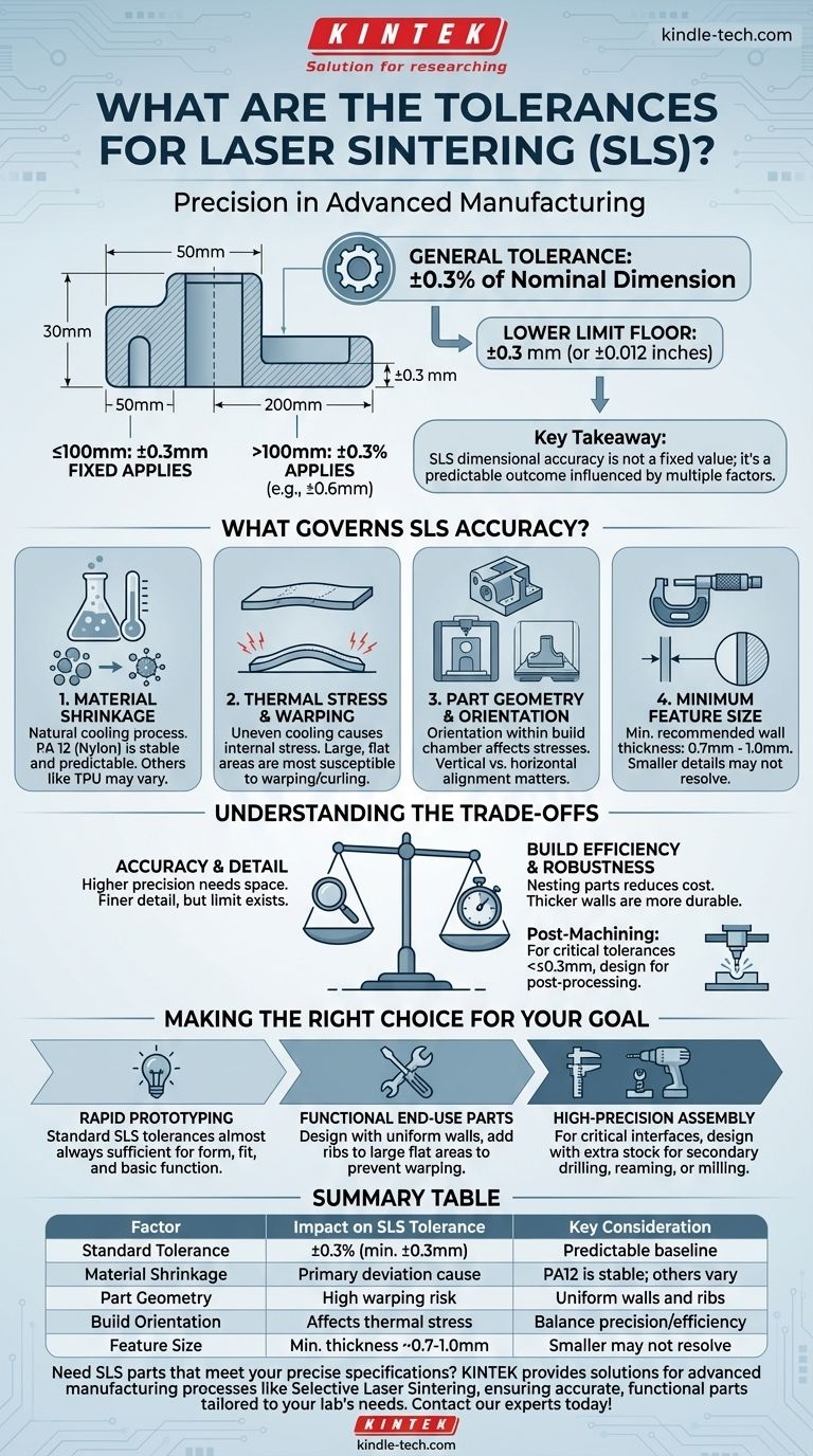
To be precise, the general tolerance for parts made with Selective Laser Sintering (SLS) is typically ±0.3% of the nominal dimension, with a lower limit of ±0.3 mm (or ±0.012 inches). This means that for any feature smaller than 100mm, a fixed tolerance of ±0.3 mm is applied, while for larger features, the percentage-based tolerance is used.
The key takeaway is that SLS dimensional accuracy is not a single, fixed value. It is a predictable outcome influenced by the part's size, its geometry, the material used, and its orientation within the build chamber.

What Governs SLS Accuracy?
Understanding the factors that influence the final dimensions of an SLS part is crucial for designing components that meet your requirements. The process is highly repeatable, but its inherent thermal nature introduces variables you must account for.
The Standard Tolerance Formula
The industry-standard guideline of ±0.3% with a ±0.3 mm floor is the starting point for any design.
For a 200 mm long part, the potential variation would be ±0.6 mm (200 mm * 0.3%). For a 50 mm part, the fixed ±0.3 mm tolerance applies, as it is greater than the percentage value (50 mm * 0.3% = 0.15 mm).
The Role of Material Shrinkage
SLS works by fusing polymer powder with a laser, which involves significant heat. As the fused part cools, the material naturally shrinks.
Materials like PA 12 (Nylon) are very stable and have predictable shrinkage rates, which are accounted for in the printing software. Other materials, like TPU (a flexible polymer), may exhibit different thermal behaviors.
Thermal Stress and Warping
Uneven cooling is the primary cause of dimensional deviation. Large, flat, or unsupported sections of a model are the most susceptible to this.
As one area cools faster than another, internal stresses build up, which can cause the part to warp or curl, especially on long, thin features. This directly impacts the final accuracy.
Part Geometry and Orientation
How a part is designed and oriented in the build chamber has a significant impact.
A long, thin part printed vertically will have different stresses and potential deviations than the same part printed flat. The orientation is chosen to minimize warping and maximize part quality.
Understanding the Trade-offs
Achieving the tightest possible tolerances requires balancing several competing factors. Simply demanding higher precision without understanding the implications can lead to unnecessary costs or design compromises.
Accuracy vs. Build Efficiency
Parts are "nested" or packed closely together in the build chamber to maximize the number of components per print run, reducing cost.
Orienting a part for the absolute best accuracy might take up more space, leading to a less efficient build and a higher per-part cost.
Feature Detail vs. Robustness
SLS can produce very fine details, but there is a limit. The minimum recommended wall thickness is typically around 0.7 mm to 1.0 mm.
Features smaller than this may not resolve properly or could be too fragile to withstand post-processing, such as the bead blasting used to clean off excess powder.
As-Printed vs. Post-Machined
The standard SLS tolerance is for the part as it comes out of the printer and is cleaned.
If a specific feature, like a precision bore for a bearing, requires a tolerance tighter than ±0.3 mm, it is common to design the part to be post-machined. This adds a manufacturing step but allows you to achieve much higher precision where it is needed most.
Making the Right Choice for Your Goal
Use these guidelines to determine if standard SLS tolerances will meet your project's needs.
- If your primary focus is rapid prototyping: Standard SLS tolerances are almost always sufficient for proving form, fit, and basic function.
- If your primary focus is functional end-use parts: Design with uniform wall thickness and add ribs to large flat areas to prevent warping and ensure you stay within the standard tolerance band.
- If your primary focus is high-precision assembly: For critical interfaces, design features with extra stock material specifically so they can be drilled, reamed, or milled in a secondary operation.
By understanding the factors that control accuracy, you can effectively design parts that leverage the speed and design freedom of SLS while meeting your critical engineering requirements.
Summary Table:
| Factor | Impact on SLS Tolerance | Key Consideration |
|---|---|---|
| Standard Tolerance | ±0.3% of dimension (min. ±0.3 mm) | Predictable baseline for most features |
| Material Shrinkage | Primary cause of deviation | PA12 is stable; others vary |
| Part Geometry | High risk of warping on large, flat areas | Design with uniform walls and ribs |
| Build Orientation | Affects thermal stress and accuracy | Balance precision with build efficiency |
| Feature Size | Minimum wall thickness ~0.7-1.0 mm | Smaller features may not resolve properly |
Need SLS parts that meet your precise specifications? KINTEK specializes in providing high-quality lab equipment and consumables, including solutions for advanced manufacturing processes like Selective Laser Sintering. Our expertise ensures you get accurate, functional parts tailored to your laboratory's unique needs—whether for prototyping or end-use applications. Contact our experts today to discuss how we can support your project with reliable performance and precise results!
Visual Guide
Related Products
- Spark Plasma Sintering Furnace SPS Furnace
- Dental Porcelain Zirconia Sintering Ceramic Furnace Chairside with Transformer
- Dental Porcelain Zirconia Sintering Ceramic Vacuum Press Furnace
- High Temperature Muffle Oven Furnace for Laboratory Debinding and Pre Sintering
- Vacuum Dental Porcelain Sintering Furnace
People Also Ask
- What is the process fundamentals of spark plasma sintering? Achieve Rapid, High-Density Material Consolidation
- What technical advantages does a Spark Plasma Sintering (SPS) furnace offer for LZP ceramics? Enhance Ionic Conductivity
- What is the difference between spark plasma sintering and flash sintering? A Guide to Advanced Sintering Methods
- Why are Spark Plasma Sintering (SPS) furnaces or hot presses utilized in the preparation of Li3PS4 solid electrolytes?
- What is the theory of spark plasma sintering? A Guide to Rapid, Low-Temperature Densification