To be precise, there is no single voltage for arcing. The common rule of thumb is that the dielectric strength of air is roughly 3,000 volts per millimeter (3 kV/mm) at sea level, but this is a vast oversimplification. The actual voltage required to initiate an arc depends on a combination of factors, including the distance between conductors, the pressure of the surrounding gas, and the shape of the electrodes.
Viewing arcing as a fixed voltage is a common misconception. The reality is that an arc occurs when the electric field strength—the voltage across a specific distance—becomes intense enough to break down the insulating medium between two conductors.
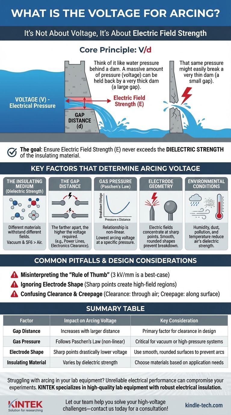
It's Not About Voltage, It's About Electric Field Strength
An electrical arc is a breakdown of an insulator, turning it into a conductor. This happens when the electrical pressure, or voltage, is too high for the insulator to withstand over a given distance.
The Core Principle: V/d
The critical factor is the electric field (E), often simplified as voltage (V) divided by distance (d).
Think of it like water pressure behind a dam. A massive amount of pressure (voltage) can be held back by a very thick dam (a large gap distance). However, that same pressure might easily break a very thin dam (a small gap).
The goal in preventing arcing is to ensure the electric field strength never exceeds the dielectric strength of the insulating material.
Key Factors That Determine Arcing Voltage
The 3 kV/mm rule of thumb only applies to a uniform electric field between two flat plates in dry, standard-pressure air. In the real world, several variables change the outcome dramatically.
The Insulating Medium (Dielectric Strength)
Every material has a different ability to withstand an electric field. Air is a decent insulator, but other materials are far better.
A vacuum, for instance, is an excellent insulator because there are very few molecules to ionize and form a conductive path. Conversely, specialized gases like Sulfur Hexafluoride (SF6) are used in high-voltage switchgear because their dielectric strength is much higher than air.
The Gap Distance
This is the most intuitive factor. The farther apart two conductors are, the higher the voltage required to create an arc between them.
This is why high-voltage power lines are spaced far apart and held high off the ground by tall towers. In electronics, this is referred to as clearance.
Gas Pressure (Paschen's Law)
The relationship between pressure and breakdown voltage is not linear. Paschen's Law describes how the breakdown voltage of a gas changes with the product of pressure and gap distance.
At very low pressures (a partial vacuum), it becomes harder to start an arc because there are fewer charge-carrying molecules available. As pressure increases, it gets easier to arc, up to a point. At very high pressures, it once again becomes much harder to arc because the dense molecules impede the flow of electrons.
Electrode Geometry
The shape of the conductors has a massive impact. Electric fields concentrate at sharp points.
A sharp solder joint or the tip of a screw can dramatically lower the voltage needed to start an arc because the electric field is intensified at that point. This is why high-voltage equipment uses large, smooth, spherical, or toroidal shapes to distribute the electric field evenly and prevent breakdown.
Environmental Conditions
Humidity, dust, pollution, and temperature all reduce the dielectric strength of air.
Water vapor is more conductive than dry air, so high humidity lowers the breakdown voltage. Similarly, dust or dirt on the surface of an insulator can provide a conductive path, leading to an arc at a much lower voltage than expected.
Common Pitfalls and Design Considerations
Relying on a single number for arcing voltage is a frequent source of failure in electrical and electronic design. Understanding the nuances is critical for building robust systems.
Misinterpreting the "Rule of Thumb"
Applying the 3 kV/mm rule blindly to a design with sharp points, high humidity, or high altitude (lower air pressure) will almost certainly lead to failure. This value should be treated as a best-case scenario, not a universal constant.
Ignoring Electrode Shape
A design can be theoretically sound based on clearance calculations, but a single sharp point on a component lead or heatsink can create a localized high-field region that initiates an arc. All conductive points must be considered.
Confusing Clearance and Creepage
Clearance is the shortest distance between two conductors through the air. Creepage is the shortest distance along the surface of an insulator.
Dirt and moisture can accumulate on a surface, making the creepage path much easier to break down than the clearance path through clean air. High-voltage PCB design requires careful attention to both.
How to Apply This to Your Project
Your approach to managing arcing depends entirely on your goal. There is no one-size-fits-all solution, only a correct application of the principles.
- If your primary focus is high-voltage product design: Prioritize calculating required clearance and creepage distances according to safety standards (like IEC 60950), selecting materials with high dielectric strength, and ensuring all conductive surfaces are smooth.
- If your primary focus is troubleshooting unexpected arcing: Investigate for contamination (dust, moisture), physical damage that may have reduced a gap, or the presence of sharp points from solder joints or component leads that may be concentrating the electric field.
- If your primary focus is working with vacuum or specialized gas systems: Do not use air-based rules of thumb. You must consult Paschen curves for your specific gas and pressure range to determine the actual breakdown voltage.
By understanding these principles, you can move from reacting to arcs to proactively designing systems that are safe, reliable, and robust.
Summary Table:
| Factor | Impact on Arcing Voltage | Key Consideration |
|---|---|---|
| Gap Distance | Increases with larger distance | Primary factor for clearance in design |
| Gas Pressure | Follows Paschen's Law (non-linear) | Critical for vacuum or high-pressure systems |
| Electrode Shape | Sharp points drastically lower voltage | Use smooth, rounded surfaces to prevent arcs |
| Insulating Material | Varies by dielectric strength (e.g., SF6 > air) | Choose materials based on application needs |
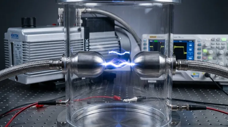
Struggling with arcing in your lab equipment? Unreliable electrical performance can compromise your experiments and data integrity. KINTEK specializes in high-quality lab equipment and consumables designed with robust electrical insulation and safety in mind. Our expertise ensures your systems operate reliably under demanding conditions. Let our team help you solve your high-voltage challenges—contact us today for a consultation!
Visual Guide