Design and Optimization of Resistance Wire
Complex Design Procedures
The design of metal tubular electric heating elements is a multifaceted and intricate process, involving a multitude of parameters that must be meticulously considered to optimize the performance of the resistance wire. The complexity arises from the interdependent nature of these parameters, which often require iterative calculations to achieve a comprehensive and accurate determination of the wire's properties. This iterative process is akin to a set of nested loops, where each calculation influences the next, necessitating a significant investment of time and effort to arrive at the optimal design.
To illustrate the complexity, consider the following key parameters that must be balanced:
| Parameter | Description |
|---|---|
| Resistivity | The electrical resistance of the material, crucial for heat generation. |
| Temperature Coefficient | The change in resistance with temperature, affecting power output. |
| Surface Load | The power density on the wire's surface, influencing heat dissipation. |
| Winding Parameters | The geometry of the wire's winding, affecting heat distribution and life. |
Each of these parameters is not isolated but interconnected, creating a web of dependencies that must be navigated carefully. For instance, changes in resistivity due to temperature fluctuations can significantly impact the surface load, which in turn affects the winding parameters. This interdependence necessitates a methodical approach, often involving repeated calculations and adjustments to fine-tune the design.
Moreover, the efficiency of this process is a common concern among technicians in the electric heating manufacturing industry. The desire to streamline calculations and reduce the time spent on iterative processes is paramount. Techniques such as quick calculation methods and the use of comprehensive parameter tables are employed to expedite the design phase. These tools allow engineers to rapidly assess and adjust key parameters, thereby improving the overall efficiency of the design procedure.
In summary, the design of metal tubular electric heating elements is a complex and iterative process, requiring careful consideration of multiple interrelated parameters. The challenge lies in balancing these parameters to achieve optimal performance, while also seeking methods to enhance the efficiency of the design process.
Basic Principles of Resistance Heating
Resistance heating is a fundamental process in converting electrical energy into thermal energy, leveraging the inherent resistance properties of conductive materials. This method is rooted in the principle that when an electric current passes through a conductor, the resistance within the material causes electrons to collide with atoms, thereby transferring kinetic energy and generating heat. This phenomenon, known as Joule heating, is a direct result of the atomic-level interactions within the material.
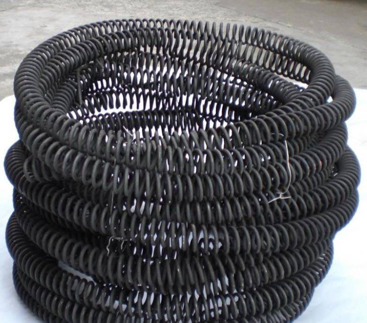
The efficiency of resistance heating is highly dependent on the material's resistivity, uniformity of resistance value, chemical stability, and high-temperature strength. Among the various materials used for resistance heating, alloy resistance wires are the most prevalent, particularly those made from nickel-chromium (Ni-Cr), ferro-chromium aluminum (Fe-Cr-Al), and molybdenum chrome-aluminum (Cr-Al-Mo) alloys. These materials are chosen for their superior resistance to oxidation and their ability to maintain structural integrity at high temperatures.
Resistance heating is not limited to wire heating; it encompasses a broader range of applications, including direct and indirect heating methods. In direct resistance heating, the material to be heated itself acts as the resistance, with electrodes passing current through it to generate heat. This method is highly efficient as the heat is produced directly within the material. Conversely, indirect resistance heating involves a separate heating element that transfers heat to the material, offering greater control over the heating process.
The versatility of resistance heating makes it applicable across numerous industries, from metal heat treatment and pottery drying to domestic cooking. The ability to achieve temperatures up to 1,000°C in specialized ovens further underscores its significance in various industrial and commercial processes. Understanding these basic principles is crucial for optimizing furnace heating element design and selection, ensuring efficient and reliable heat generation.
Key Parameters and Calculations
Resistivity and Resistance Value
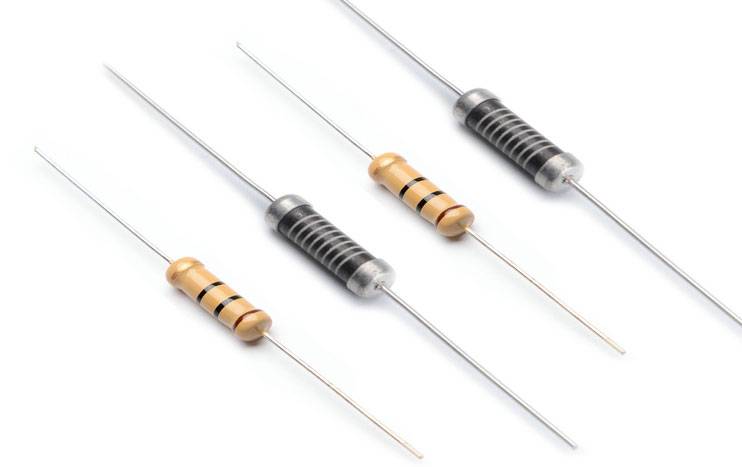
The resistivity of a resistance wire, often referred to as the coefficient of resistance or specific resistance, is a fundamental electrical parameter that quantifies a conductor's opposition to the flow of electric current. This parameter is crucial in determining the resistance of a conductor, and the relationship between resistivity and resistance can be mathematically expressed as:
[ R = \frac{\rho \cdot C}{S} ]
where:
- ( R ) is the resistance,
- ( \rho ) is the resistivity,
- ( C ) is the length of the conductor,
- ( S ) is the cross-sectional area of the conductor.
Resistivity is influenced by several factors, including the chemical composition, metallurgical structure, and operating temperature of the alloy. These factors collectively contribute to the material's ability to resist current flow, making resistivity a critical datum for calculating the resistance value of resistance wires of various specifications.
By understanding the resistivity of a material, one can easily compute the meter resistance—the resistance value per meter length—for different specifications of resistance wires. This calculation is essential for designing and optimizing resistance wires used in applications such as muffle furnaces, ensuring that the wires perform efficiently and reliably under various operating conditions.
Temperature Coefficient of Resistance
When the temperature of an alloy resistance wire changes, its resistance value (resistivity) also undergoes a corresponding alteration. This change is quantified by the resistance temperature coefficient, which is a critical parameter in the design of tubular electric heating elements. The resistance temperature coefficient, denoted as ( \alpha ), is defined as the fractional change in resistance per degree change in temperature.
The relationship between the resistivity ( \rho ) at an operating temperature ( T ) and the resistivity ( \rho_{20} ) at 20°C can be expressed using the resistivity correction coefficient ( C_t ):
[ C_t = \frac{\rho_t}{\rho_{20}} ]
Where:
- ( \rho_t ) is the resistivity at temperature ( T ).
- ( \rho_{20} ) is the resistivity at 20°C.
If the resistance temperature coefficient ( C_t ) for a specific grade of resistance wire is known, the resistance value at any temperature can be calculated using the formula:
[ R_t = R_{20} \cdot C_t ]
Where:
- ( R_t ) is the resistance at temperature ( T ).
- ( R_{20} ) is the resistance at 20°C.
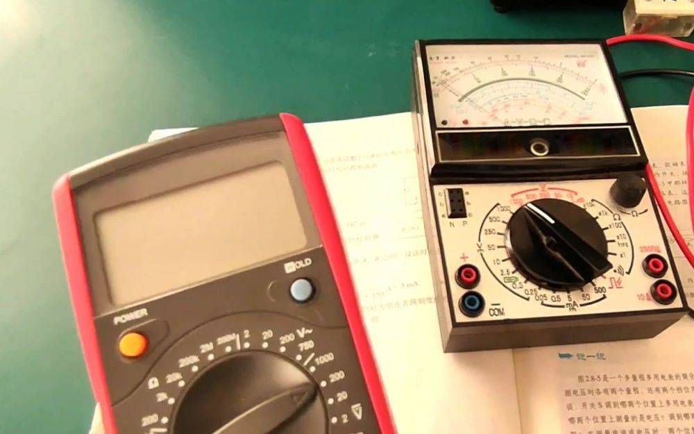
In practical applications, the temperature coefficient of resistance directly impacts the power output of the heating element. Designers must consider the approximate change in resistance as depicted in the temperature-resistance curve. Additionally, simulations and actual tests under working conditions are essential to validate the resistance values at different temperatures. This involves comparing the resistance at room temperature with the resistance at the operating temperature, using the measured coefficient to ascertain the resistance state at room temperature. This method ensures that the resistance value of the finished product aligns with the design specifications.
For instance, if the resistance wire is subjected to a temperature increase from 20°C to 500°C, the change in resistance can be significant. By knowing the temperature coefficient, engineers can predict and adjust the resistance value to maintain the desired power output and operational efficiency. This proactive approach is crucial for optimizing the performance of the heating element in various industrial applications, such as muffle furnaces, where precise temperature control is paramount.
Surface Load and Winding Parameters
Silk surface load, measured in W/cm², is a critical parameter in the design of electric heating elements. It represents the total electrical power per unit surface area of the heating wire. The selection of the appropriate surface load is influenced by the heat dissipation conditions of the components. In environments with poor heat dissipation, a lower surface load is advisable to prevent overheating and ensure the longevity of the heating element. Conversely, in situations with better heat dissipation, a higher surface load can be tolerated, allowing for more efficient heating.
The heat dissipation conditions are contingent upon several factors, including the nature of the heated substance, the size of the object, fluid flow, and air wind speed. These variables collectively determine the effective surface load and must be considered comprehensively to avoid inaccuracies in the design process.
The calculation of the surface load can be performed using the formula:
[ W/cm^2 = \frac{P}{D \cdot \pi \cdot L} ]
where:
- ( W ) is the surface load in W/cm²,
- ( P ) is the power in watts,
- ( D ) is the diameter of the heating wire in cm,
- ( \pi ) is a constant (approximately 3.14159),
- ( L ) is the length of the heating wire in cm.
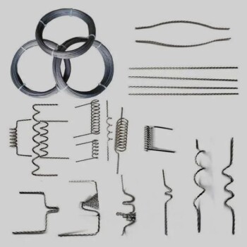
Winding parameters, such as the winding circle diameter and the winding distance (pitch), are crucial for optimizing the performance of the heating element. The pitch, which is the distance between each turn of the spiral resistance wire, significantly impacts the uniformity of heat generation, the compactness of the winding, and the overall lifespan of the product. Typically, the pitch is expressed as a multiple of the diameter of the resistance wire to standardize the design process and ensure consistent performance across different applications.
In summary, the careful selection and calculation of surface load and winding parameters are essential for the effective design and operation of electric heating elements. These parameters must be tailored to the specific conditions of the application to achieve optimal performance and durability.
Quick Calculation Techniques
Quick Calculation of Meter Resistance
To facilitate quick calculations of meter resistance, we can use a standardized base value derived from a common specification. For instance, the meter resistance of a Cr25AC5 grade wire with a diameter of Φ0.2mm is approximately 45.2Ω. By memorizing this base value, you can easily extrapolate the meter resistance for wires of different diameters.
The calculation process involves a few straightforward steps:
-
Determine the Radius: Calculate the radius of the wire you are working with. For example, if the wire diameter is Φ0.3mm, the radius would be 0.15mm.
-
Square the Radius: Compute the square of the radius. For our example, ( (0.15)^2 = 0.0225 ).
-
Apply the Base Value: Use the base meter resistance value (45.2Ω) and adjust it according to the radius squared. Specifically, multiply 45.2 by 100 times the radius squared. For our example, this would be ( 45.2 \times 100 \times 0.0225 = 101.7Ω ).
This method allows for rapid estimation of meter resistance, streamlining the design process for muffle furnace resistance wires. By simplifying these calculations, technicians can optimize their designs more efficiently, reducing the time and effort required for parameter adjustments.
Quick Check Table for Comprehensive Parameters
The Quick Check Table is meticulously crafted using the Cr25AC5 material as its foundational basis. This table is designed to streamline the process of deriving comprehensive parameters by correlating key product specifications such as rated voltage, rated power, tube diameter, and the length of the heating zone. By inputting these specifications, users can swiftly identify the necessary data correlations, thereby facilitating a more efficient and accurate calculation process.
To further elucidate its utility, consider the following steps:
- Input Specifications: Begin by entering the product's rated voltage, rated power, tube diameter, and the length of the heating zone into the table.
- Data Correlation: The table instantly correlates these inputs to provide you with the essential data points needed for your calculations.
- Comprehensive Parameters: With these data points in hand, a simple calculation can yield the comprehensive parameters required for your design or analysis.
This table is not just a tool for quick data retrieval but also a strategic asset that enhances the efficiency and precision of your resistance wire design processes.
Related Products
- 1800℃ Muffle Oven Furnace for Laboratory
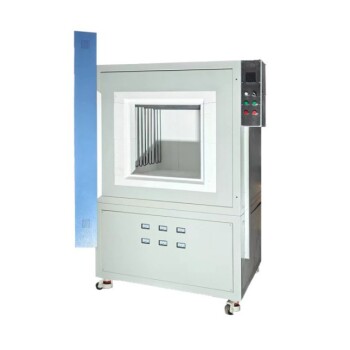
- High Temperature Muffle Oven Furnace for Laboratory Debinding and Pre Sintering
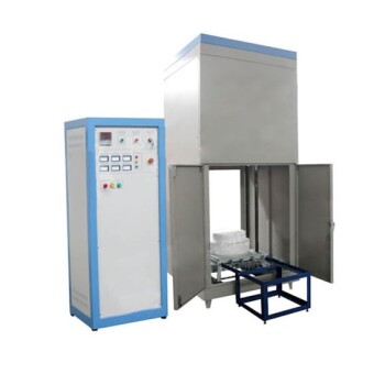
- Laboratory Muffle Oven Furnace Bottom Lifting Muffle Furnace
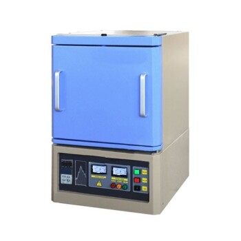
- 1200℃ Muffle Furnace Oven for Laboratory
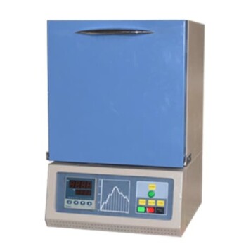
- 1700℃ Muffle Oven Furnace for Laboratory
Related Articles
- Factors Influencing the Performance and Price of a Muffle Furnace
- Selection of Muffle Furnace: Key Considerations
- Substances Suitable for Calcination in a High-Temperature Muffle Furnace
- Temperature Control Accuracy of High Temperature Experimental Chamber Muffle Furnace
- Calibration Methods for High-Temperature Muffle Furnaces