Radio frequency (RF) power is the primary catalyst for ionization in the Plasma Enhanced Chemical Vapor Deposition (PECVD) process. It provides the energy necessary to break down precursor gases into reactive ions and free radicals, directly determining the bombardment energy that shapes the density and quality of the resulting film.
Core Takeaway: Increasing RF power enhances film quality by intensifying ion bombardment, but this benefit has a physical limit. Once the reaction gas is fully ionized, the process reaches a saturation point where the deposition rate stabilizes and further power increases yield diminishing returns.
The Mechanics of RF Power in Deposition
Igniting the Plasma
In a typical PECVD chamber, an electrical discharge (often 100–300 eV) is applied between electrodes to ignite the plasma. This creates a glowing sheath around the substrate.
The RF power drives the collision of high-energy electrons with precursor gas molecules. This energy transfer initiates the chemical reactions required to grow the thin film.
Enhancing Film Quality Through Bombardment
Higher RF power directly translates to increased bombardment energy of the ions striking the substrate surface.
This aggressive bombardment acts like a microscopic hammer, packing the deposited atoms more tightly.
Consequently, higher power generally leads to films with smoother morphology, improved crystallinity, and lower sheet resistance.
The Saturation Phenomenon
Reaching the Ionization Limit
There is a "ceiling" to the effectiveness of simply increasing power.
As you increase RF power, you eventually reach a state where the reaction gas becomes completely ionized.
Stabilization of Deposition Rate
At this high-energy state, the concentration of free radicals reaches a saturation point.
Once this occurs, the precipitation (deposition) rate stabilizes. Adding more power beyond this threshold does not increase the deposition rate; it only adds excess energy to the system.
The Role of Operating Frequency
Impact on Uniformity
While power magnitude affects density, the frequency of the RF supply (typically 50kHz to 13.56MHz) dictates uniformity.
Operating at higher frequencies creates a more consistent electric field across the plate.
This minimizes the difference in deposition speed between the center and the edge of the substrate, resulting in superior film uniformity.
Understanding the Trade-offs
The Risk of Substrate Damage
The same ion bombardment that creates denser films can become a liability if unchecked.
Excessively high power or frequency results in very strong ion impacts. This can cause physical damage to the substrate, compromising the integrity of the device being manufactured.
Balancing Density vs. Integrity
You must balance the need for a dense, high-quality film against the voltage tolerance of your substrate.
Pushing power to the saturation point ensures maximum ionization, but crossing into excessive bombardment risks defects.
Making the Right Choice for Your Goal
To optimize your PECVD process, you must tune the RF power based on your specific film requirements:
- If your primary focus is Film Density and Quality: Increase the RF power magnitude to maximize ion bombardment, ensuring you stay just below the threshold of substrate damage.
- If your primary focus is Thickness Uniformity: Utilize a higher operating frequency (closer to 13.56MHz) to ensure a consistent electric field across the entire wafer.
- If your primary focus is Process Efficiency: Identify the saturation point where the deposition rate stabilizes, and do not exceed this power level to avoid wasted energy.
Success in PECVD lies in finding the "sweet spot" where the gas is fully ionized, but the substrate remains undamaged.
Summary Table:
| Parameter | Influence on PECVD Process | Result of Increase |
|---|---|---|
| RF Power Magnitude | Ionization energy & bombardment | Denser films, smoother morphology, higher crystallinity |
| Deposition Rate | Precursor gas breakdown | Increases until the saturation point (full ionization) |
| RF Frequency | Electric field consistency | Improved thickness uniformity across the substrate |
| Ion Bombardment | Physical impact on atoms | Tighter packing of atoms; risk of substrate damage if excessive |
Elevate Your Thin Film Precision with KINTEK
Optimizing RF power is critical for achieving the perfect balance between film density and substrate integrity. KINTEK specializes in high-performance laboratory equipment, including advanced PECVD and CVD systems, specifically engineered for precise material deposition.
Whether you are conducting battery research, developing semiconductors, or exploring material science, our comprehensive portfolio—ranging from high-temperature furnaces and vacuum systems to PTFE consumables and ceramic crucibles—provides the reliability your lab demands.
Ready to refine your deposition process? Contact KINTEK today to speak with our experts about our tailored solutions for your research and manufacturing needs!
Related Products
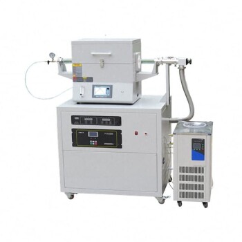
- RF PECVD System Radio Frequency Plasma-Enhanced Chemical Vapor Deposition RF PECVD
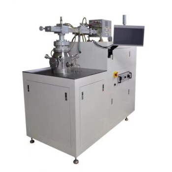
- Chemical Vapor Deposition CVD Equipment System Chamber Slide PECVD Tube Furnace with Liquid Gasifier PECVD Machine
- Inclined Rotary Plasma Enhanced Chemical Vapor Deposition PECVD Equipment Tube Furnace Machine
- Inclined Rotary Plasma Enhanced Chemical Vapor Deposition PECVD Equipment Tube Furnace Machine
- 915MHz MPCVD Diamond Machine Microwave Plasma Chemical Vapor Deposition System Reactor
People Also Ask
- What is plasma CVD? Unlock Low-Temperature Thin Film Deposition for Sensitive Materials
- What is the role of RF-PECVD in VFG preparation? Mastering Vertical Growth and Surface Functionality
- What is plasma enhanced chemical vapour deposition process? Unlock Low-Temperature, High-Quality Thin Films
- Why is a Matching Network Indispensable in RF-PECVD for Siloxane Films? Ensure Stable Plasma and Uniform Deposition
- What is plasma chemical vapor deposition? A Low-Temperature Thin Film Coating Solution