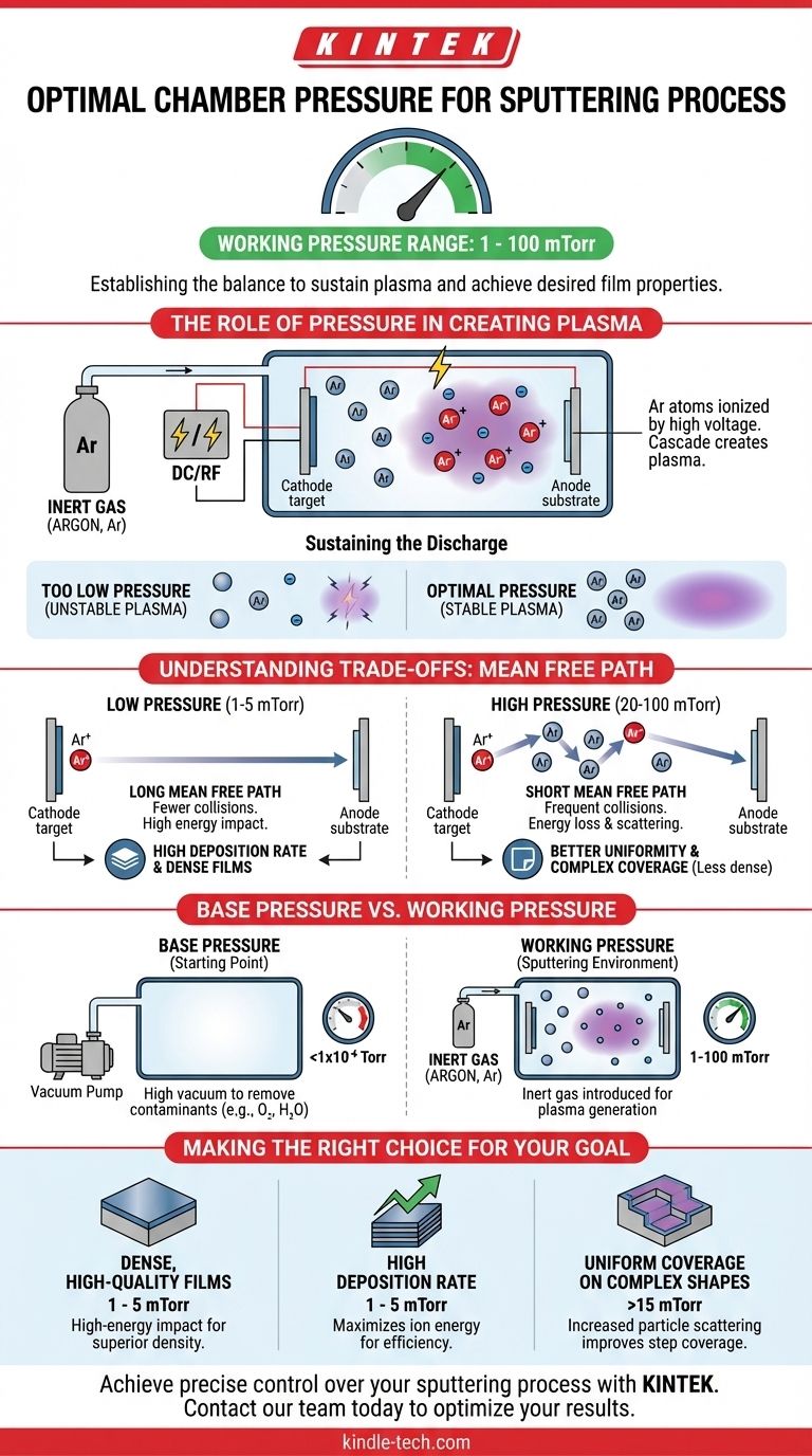
To initiate the sputtering process, you must first introduce an inert gas into a high-vacuum chamber, raising the pressure to a "working pressure" typically in the range of 1 to 100 millitorr (mTorr). This pressure is required to generate and sustain the plasma that bombards the target material. Without achieving this specific pressure range, a stable plasma discharge cannot be formed.
The core challenge is not finding a single correct pressure, but establishing a balance. The chamber pressure must be high enough to provide sufficient gas atoms to sustain a plasma, yet low enough to allow the resulting ions to accelerate and strike the target with high energy without excessive collisions.
The Role of Pressure in Creating Plasma
Sputtering does not happen in a perfect vacuum. It relies on a carefully controlled, low-pressure gaseous environment to function. The pressure directly dictates the density of gas atoms available to create and sustain the process.
The Need for a Gaseous Medium
Sputtering uses a process gas, almost always an inert gas like Argon (Ar), as the source for the ions that will do the sputtering. At the start, the chamber is evacuated to a very high vacuum to remove contaminants. Then, Argon is flowed in to reach the desired working pressure.
Igniting the Plasma
Once the Argon is present, a high voltage (for DC sputtering) or radio frequency (RF) power is applied. This strong electric field energizes free electrons in the chamber, which then collide with the neutral Argon atoms.
These collisions are energetic enough to knock electrons off the Argon atoms, creating positively charged Argon ions (Ar⁺) and more free electrons. This cascade of ionization is what ignites and forms the plasma—a quasi-neutral cloud of ions, electrons, and neutral atoms.
Sustaining the Discharge
To keep the plasma "lit," you need a sufficient number of Argon atoms in the chamber. If the pressure is too low, there are too few atoms, and an electron is unlikely to hit one before striking a chamber wall. This makes the plasma unstable or impossible to sustain.
Understanding the Trade-offs of Sputtering Pressure
The choice of working pressure is a critical parameter that involves significant trade-offs affecting deposition rate, film quality, and uniformity. The controlling physical principle behind this is the mean free path.
Mean Free Path: The Critical Concept
Mean free path (MFP) is the average distance a particle (like an Argon ion or a sputtered target atom) travels before colliding with another particle.
A higher pressure means more gas atoms are present, leading to a shorter mean free path. Conversely, a lower pressure means fewer gas atoms and a longer mean free path.
The Impact of Low Pressure
Operating at the lower end of the working pressure range (e.g., 1-5 mTorr) results in a long mean free path. Argon ions accelerate over longer distances, hitting the target with maximum energy.
This is beneficial for achieving high deposition rates and creating dense, high-quality films, as both the ions and the sputtered target atoms travel to their destinations with minimal interruption.
The Impact of High Pressure
Operating at a higher pressure (e.g., 20-100 mTorr) results in a short mean free path. Ions collide frequently with neutral Argon atoms on their way to the target, losing energy.
This leads to a lower sputtering rate. Furthermore, the sputtered target atoms also collide with gas atoms on their way to the substrate, scattering them. This scattering can improve film uniformity over complex, non-flat surfaces but often results in a less dense film structure.
Base Pressure vs. Working Pressure: A Key Distinction
It is critical to distinguish between the two pressure regimes in a sputtering system. Confusing them is a common source of error.
Base Pressure (The Starting Point)
This is the initial, high-vacuum state of the chamber before the process gas is introduced. It is typically below 1x10⁻⁶ Torr. The goal of the base pressure is to remove contaminants like oxygen, water vapor, and nitrogen, which can react with and ruin the deposited film.
Working Pressure (The Sputtering Environment)
This is the pressure achieved after throttling the high-vacuum pump and flowing in the inert process gas. This is the 1 to 100 mTorr range where the plasma is generated and the actual sputtering takes place.
Making the Right Choice for Your Goal
The ideal working pressure is determined entirely by the desired outcome of your deposition. There is no single "best" pressure, only the right pressure for a specific application.
- If your primary focus is dense, high-quality films: Operate at a lower working pressure (e.g., 1-5 mTorr) to ensure particles arrive at the substrate with high energy.
- If your primary focus is the highest possible deposition rate: A lower working pressure is generally preferred, as it maximizes the energy of ions striking the target.
- If your primary focus is uniform coverage on a complex shape: A higher working pressure (e.g., >15 mTorr) may be necessary to increase particle scattering and improve step coverage.
Ultimately, controlling chamber pressure is about controlling the energy and trajectory of particles to achieve your desired material properties.
Summary Table:
| Goal | Recommended Pressure Range | Key Outcome |
|---|---|---|
| Dense, High-Quality Films | 1 - 5 mTorr | High-energy particle impact for superior film density. |
| High Deposition Rate | 1 - 5 mTorr | Maximizes ion energy for efficient sputtering. |
| Uniform Coverage on Complex Shapes | >15 mTorr | Increased particle scattering improves step coverage. |
Achieve precise control over your sputtering process with KINTEK.
Whether your goal is creating dense, high-purity films or achieving uniform coatings on complex substrates, selecting the correct chamber pressure is critical. KINTEK specializes in providing advanced lab equipment and consumables tailored to your specific deposition challenges.
Our experts can help you configure a system that delivers the exact pressure control needed for your application, ensuring optimal film quality and process efficiency.
Ready to optimize your sputtering results? Contact our team today to discuss your laboratory's needs and discover how KINTEK's solutions can enhance your research and production.
Visual Guide
Related Products
- Split Chamber CVD Tube Furnace with Vacuum Station Chemical Vapor Deposition System Equipment Machine
- Customer Made Versatile CVD Tube Furnace Chemical Vapor Deposition Chamber System Equipment
- Chemical Vapor Deposition CVD Equipment System Chamber Slide PECVD Tube Furnace with Liquid Gasifier PECVD Machine
- Multi Heating Zones CVD Tube Furnace Machine Chemical Vapor Deposition Chamber System Equipment
People Also Ask
- How does a CVD tube furnace inhibit the sintering of silver supports? Boost Membrane Durability and Performance
- What is a major limitation of standard CVD? Solve the Thermal Barrier with Advanced Coating Solutions
- What temperature is maintained in CVD? Unlocking the High-Heat Process for Superior Coatings
- What is a split tube furnace? Unlock Unmatched Access for Complex Lab Setups
- How does a tube CVD reactor facilitate N-CNT growth? Master Precision Synthesis on Carbon Paper