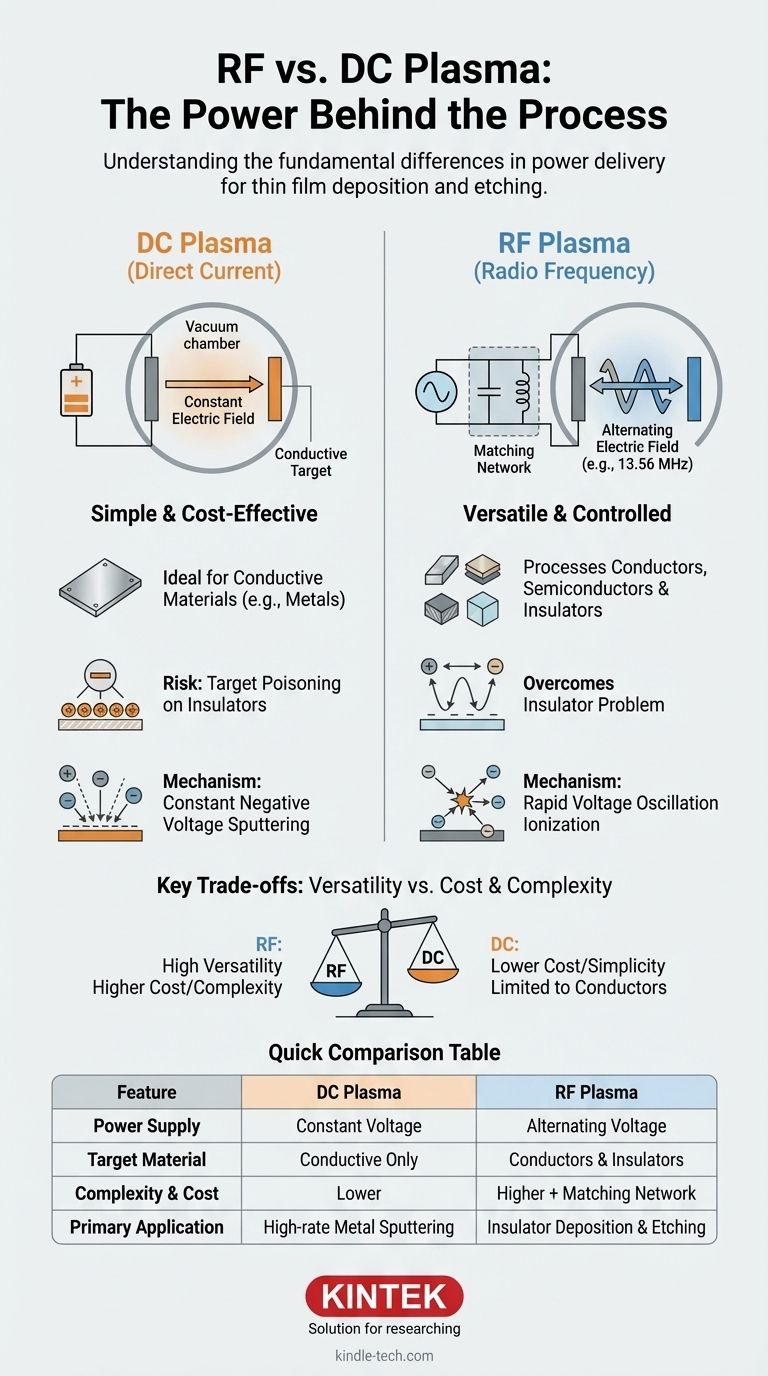
At its core, the difference between Radio Frequency (RF) and Direct Current (DC) plasma lies in the type of power supply used to generate and sustain the plasma. A DC system uses a constant voltage to create a steady electric field, while an RF system uses an alternating voltage that rapidly oscillates the electric field, typically at a frequency of 13.56 MHz. This fundamental difference in power delivery dictates which materials can be processed and determines the overall complexity and cost of the system.
The central takeaway is one of versatility versus simplicity. DC plasma is a simple, cost-effective method ideal for processing conductive materials. RF plasma is a more complex and versatile technique required for processing non-conductive or insulating materials.
The Fundamentals of Plasma Generation
The Basic Principle: Energizing a Gas
Plasma, often called the fourth state of matter, is an ionized gas. It is created by adding a large amount of energy to a neutral gas (like Argon) in a vacuum chamber, causing its atoms to release electrons.
The result is a highly energetic soup of positively charged ions, negatively charged electrons, and neutral gas atoms. This energized state is what enables processes like thin film deposition and etching.
The Role of the Electric Field
To create and sustain this plasma, an electric field is applied. This field accelerates free electrons to high speeds. These high-energy electrons then collide with neutral gas atoms, knocking more electrons loose in an avalanche effect that ignites and sustains the plasma.
Understanding DC Plasma
The DC Mechanism: A Constant Field
In a DC system, a constant, negative voltage is applied to a target material, which acts as the cathode. A nearby anode, often the chamber wall itself, is held at ground potential.
This creates a steady, one-way electric field. Positively charged ions from the plasma are accelerated by this field and bombard the target material, physically knocking atoms off its surface in a process known as sputtering.
The Critical Limitation: Conductive Targets Only
DC plasma requires the target material to be electrically conductive. If an insulating (dielectric) target is used, the positive ions bombarding it will accumulate on its surface.
This buildup of positive charge, known as target poisoning, quickly neutralizes the negative voltage of the cathode. The electric field collapses, and the plasma extinguishes.
Understanding RF Plasma
The RF Mechanism: An Oscillating Field
RF plasma systems solve the insulator problem by using an alternating power supply. The voltage on the target rapidly switches between positive and negative millions of times per second (typically at 13.56 MHz).
Electrons, being very light, can respond to this rapid oscillation. They are accelerated back and forth, gaining enough energy from the oscillating field to cause ionizing collisions and sustain the plasma.
Overcoming the Insulator Problem
Because the voltage on the target is only briefly positive during each cycle, there is not enough time for a significant layer of charge to build up and kill the plasma.
This allows an RF plasma to be sustained in front of an insulating material, making it the essential choice for depositing dielectric films like silicon dioxide (SiO₂) or aluminum oxide (Al₂O₃).
The Added Complexity: The Matching Network
RF systems are more complex than their DC counterparts. They require an impedance matching network—a box of capacitors and inductors—between the RF power supply and the chamber.
This network is crucial for ensuring that the maximum amount of power is transferred from the generator into the plasma, rather than being reflected back. It adds cost and another layer of process control.
Understanding the Key Trade-offs
Versatility vs. Cost
RF is the clear winner in versatility. It can process nearly any material, including conductors, semiconductors, and insulators. This flexibility, however, comes at a higher equipment cost and complexity due to the RF generator and matching network.
DC systems are far simpler and less expensive. If your application only involves sputtering conductive metals, a DC system is the more economical and straightforward choice.
Deposition Rate and Control
For sputtering metals, DC systems often provide higher deposition rates than RF systems under similar conditions. This is because the power transfer mechanism is more direct.
However, RF provides additional control parameters, such as the self-bias voltage that develops on the target surface, which can be used to fine-tune film properties and ion energy during etching.
Application Suitability
The choice is almost always dictated by the material. Sputtering metals like aluminum, titanium, or copper is a classic DC sputtering application.
Depositing insulating films or performing reactive ion etching (RIE) on substrates like silicon wafers are classic RF plasma applications.
Choosing the Right Plasma Source for Your Application
Your choice between DC and RF plasma is determined almost entirely by the material you need to process and your budget.
- If your primary focus is sputtering conductive metals at a high rate: DC plasma is the most cost-effective and efficient tool for the job.
- If your primary focus is depositing insulating materials (dielectrics): RF plasma is the necessary and standard industry solution.
- If your primary focus is plasma etching or modifying polymer surfaces: RF plasma offers the material versatility and process control required for these advanced applications.
- If your primary focus is minimizing equipment cost for simple metal coatings: A DC system is your most direct and economical path.
By understanding how each power source interacts with your material, you can confidently select the technology that directly aligns with your process goals.
Summary Table:
| Feature | DC Plasma | RF Plasma |
|---|---|---|
| Power Supply | Constant Voltage | Alternating Voltage (13.56 MHz) |
| Target Material | Conductive Materials Only | Conductors, Semiconductors, and Insulators |
| Complexity & Cost | Lower | Higher (requires matching network) |
| Primary Application | High-rate sputtering of metals | Sputtering insulators, Plasma Etching (RIE) |
Still Unsure Which Plasma Source is Right for Your Process?
The choice between RF and DC plasma is critical for achieving optimal results in thin film deposition, etching, and surface modification. KINTEK specializes in lab equipment and consumables, serving laboratory needs with expert guidance and reliable solutions.
Let our experts help you select the perfect system for your specific materials and budget. We can provide detailed recommendations for DC sputtering systems for metal coatings or versatile RF plasma systems for dielectric films and advanced etching.
Contact us today to discuss your application and receive a personalized consultation!
Visual Guide