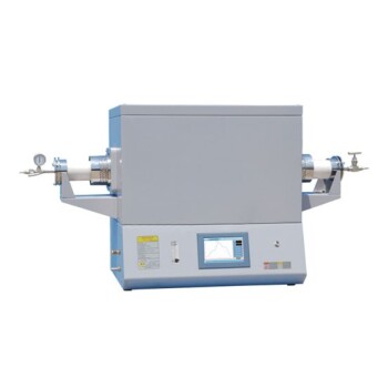
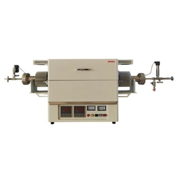
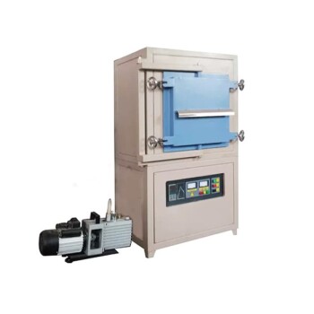
A laboratory tube furnace functions as a controlled simulation environment. It evaluates the resistance of rare earth catalysts to impurities by replicating industrial flue gas temperatures—typically between 100 and 500 degrees Celsius—while exposing the material to a precise mixture of nitrogen oxides (NO), ammonia (NH3), and contaminants like alkali or heavy metals.
By isolating the catalyst within a constant temperature zone and introducing a synthesized gas stream, researchers can accurately distinguish between thermal performance and chemical deactivation caused by specific impurities.
The Mechanics of the Evaluation System
Simulating Industrial Thermal Conditions
The primary role of the tube furnace in a Selective Catalytic Reduction (SCR) evaluation system is thermal regulation. It creates a stable environment that mirrors the specific heat conditions found in industrial processes.
For rare earth catalysts, maintaining a rigorous temperature profile is critical. The furnace operates within a range of 100 to 500 degrees Celsius, ensuring the catalyst is tested at the exact process temperature intended for its final application.
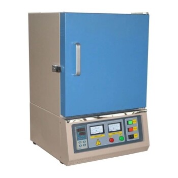
The Constant Temperature Zone
Within the furnace tube, there is a designated region known as the constant temperature zone. This is where the catalyst sample is positioned.
Placing the catalyst here eliminates temperature gradients that could skew data. It ensures that the entire sample is subjected to uniform heat, making the resulting efficiency data reliable and reproducible.
Assessing Resistance to Impurities
Introducing the Simulated Atmosphere
Once the thermal baseline is established, the system introduces a simulated flue gas. This gas stream is a complex mixture designed to replicate the chemical makeup of real-world emissions.
It typically contains the standard reactants for SCR (NO and NH3) alongside specific impurities. These impurities usually include alkali metals or heavy metals, which are known to poison catalysts.
Determining Deactivation Patterns
The core objective is to observe how the catalyst behaves when these impurities are present. By keeping the temperature constant, researchers can isolate the chemical variables.
They measure the catalytic efficiency over time to see how quickly performance degrades. This allows for the identification of specific deactivation patterns, revealing exactly how robust the rare earth catalyst is against the contaminants it will face in the field.
Understanding the Trade-offs
The Limits of Simulation
While a tube furnace offers precision, it relies entirely on the accuracy of the simulated gas mixture. The evaluation is only as good as the input; if the synthesized flue gas does not perfectly match the complexity of actual industrial emissions, the results may vary from real-world performance.
Temperature Range Constraints
The specific system described operates effectively between 100 and 500 degrees Celsius.
If the target industrial application involves temperatures exceeding this range (extreme high-heat processes), this standard evaluation setup may not provide relevant data regarding the catalyst's thermal stability or resistance properties.
Making the Right Choice for Your Goal
To maximize the value of your evaluation, align your testing parameters with your specific objectives:
- If your primary focus is defining catalyst lifespan: Prioritize long-duration tests within the constant temperature zone to map out the complete deactivation pattern over time.
- If your primary focus is process compatibility: Ensure the furnace temperature is set to match your exact industrial exhaust temperature (e.g., exactly 350°C) rather than sweeping across the entire range.
Ultimately, the tube furnace transforms a complex industrial variable into a controlled laboratory constant, empowering you to predict failure before it happens in the field.
Summary Table:
| Feature | Specification/Detail |
|---|---|
| Temperature Range | 100°C to 500°C |
| Primary Function | Thermal regulation & simulation of industrial flue gas |
| Sample Location | Constant temperature zone (eliminates gradients) |
| Simulated Gases | NO, NH3, and contaminants (alkali/heavy metals) |
| Key Metric | Catalytic efficiency & deactivation patterns over time |
Elevate Your Catalyst Research with KINTEK Precision
Don't let industrial impurities compromise your catalytic performance. KINTEK specializes in high-performance laboratory tube furnaces and rotary kilns designed to provide the stable thermal environments required for rigorous catalyst evaluation.
Whether you are developing rare earth catalysts or studying deactivation patterns in SCR systems, our comprehensive range of laboratory equipment—from crushing and milling systems to high-temperature furnaces and CVD systems—ensures your data is reliable and reproducible.
Ready to optimize your lab's testing capabilities? Contact our technical experts today to find the perfect furnace solution for your specific research goals.
References
- Xue Bian, Wenyuan Wu. Effects of Flue Gas Impurities on the Performance of Rare Earth Denitration Catalysts. DOI: 10.3390/catal12080808
This article is also based on technical information from Kintek Solution Knowledge Base .
Related Products
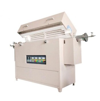
- 1700℃ Laboratory High Temperature Tube Furnace with Alumina Tube
- Multi Heating Zones CVD Tube Furnace Machine Chemical Vapor Deposition Chamber System Equipment
- High Temperature Alumina (Al2O3) Furnace Tube for Engineering Advanced Fine Ceramics
- Customer Made Versatile CVD Tube Furnace Chemical Vapor Deposition Chamber System Equipment
- 1400℃ Laboratory High Temperature Tube Furnace with Alumina Tube
People Also Ask
- What is the significance of a tube furnace in NiTiCu sintering? Achieve Precise Densification and Phase Stability
- What are the primary applications of muffle and tube furnaces in photocatalysts? Optimize Metal Loading & Support Synthesis
- How does a high-temperature tube furnace influence 253MA steel? Master Microstructure & High-Temp Creep Resistance
- Why is a high-temperature tube furnace required for the production of biochar from tobacco straw? Expert Pyrolysis Guide
- What roles does a high-temperature tube furnace play in the synthesis of N/O co-doped carbon? Master Precise Doping