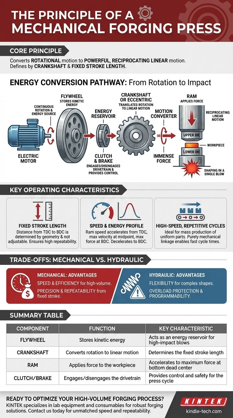
At its core, a mechanical forging press operates by converting the continuous rotational motion of a motor into a powerful, reciprocating linear motion. This transformation is achieved through a mechanical drivetrain, where a large flywheel stores kinetic energy that is then transferred via a clutch and crankshaft to drive a ram downwards with immense force. The entire process is a precisely engineered sequence of energy storage and release.
The defining principle of a mechanical press is its use of a crankshaft mechanism to deliver a rapid, high-impact blow with a fixed stroke length. This makes it exceptionally fast and repeatable for high-volume production but limits its flexibility compared to other press types.
The Energy Conversion Pathway: From Rotation to Impact
To truly understand the principle, you must follow the flow of energy through the machine's core components.
The Prime Mover: The Electric Motor
It all begins with a high-power electric motor. The motor's sole job is to run continuously, spinning a heavy flywheel and acting as the constant energy source for the entire system.
The Energy Reservoir: The Flywheel
The flywheel is a massive, heavy wheel that spins at high speed. Its primary function is to store kinetic energy. This stored energy allows the press to deliver a force far greater than what the motor could provide directly during the brief moment of impact.
The Control Mechanism: The Clutch and Brake
The clutch is the critical link that engages the spinning flywheel with the rest of the drivetrain, initiating the press stroke. When the clutch is disengaged, a brake is applied, stopping the ram's motion, typically at the top of its stroke, ensuring safety and control.
The Motion Converter: The Crankshaft or Eccentric
This is the heart of the machine. The rotational energy from the engaged clutch turns a crankshaft or an eccentric gear. Much like the crankshaft in an automobile engine, this component translates pure rotation into the up-and-down (linear) motion of the ram.
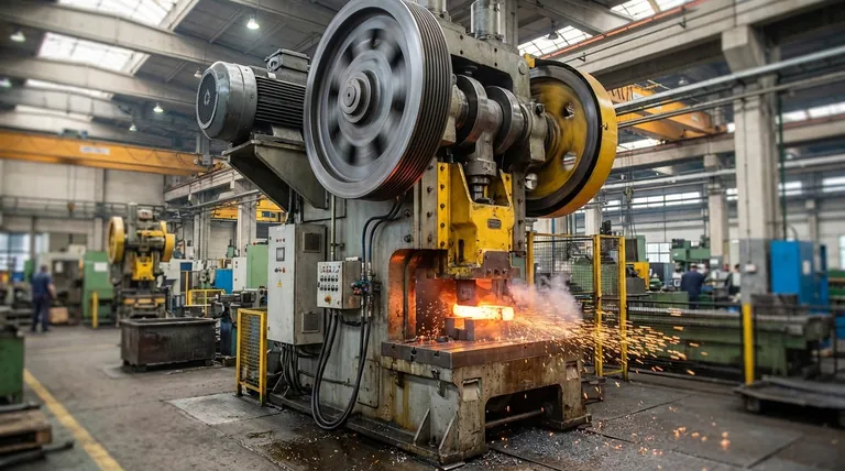
The Force Applicator: The Ram and Die
The ram (also called the slide) is the moving component that holds the upper forging die. Driven by the crankshaft, it travels down a fixed path, striking the workpiece (a heated metal billet) that rests on the stationary lower die, shaping it in a single, powerful blow.
Key Operating Characteristics
The mechanical nature of the press dictates its unique performance profile.
Fixed Stroke Length
The distance the ram travels from its highest point (Top Dead Center) to its lowest point (Bottom Dead Center) is determined by the physical geometry of the crankshaft. This fixed stroke length is not adjustable during operation, which ensures high repeatability.
Speed and Energy Profile
The ram's speed is not constant. It accelerates from the top of its stroke, reaches maximum velocity at the midpoint, and decelerates to zero as it approaches the bottom. Consequently, the maximum rated tonnage is only available at or very near the Bottom Dead Center (BDC) of the stroke.
High-Speed, Repetitive Cycles
The purely mechanical linkage allows for extremely fast and consistent cycle times. This makes the mechanical press the undisputed choice for mass production where millions of identical parts are required.
Understanding the Trade-offs: Mechanical vs. Hydraulic
No single technology is perfect for every application. Understanding the trade-offs is crucial for proper equipment selection.
Advantage: Speed and Efficiency
For high-volume production of relatively simple parts, a mechanical press is significantly faster and more energy-efficient per part than a hydraulic press.
Advantage: Precision and Repeatability
The fixed stroke guarantees that every part is forged under dimensionally identical conditions, leading to exceptional consistency and tight tolerances.
Limitation: Lack of Flexibility
The fixed stroke and the fact that full force is only available at the bottom make mechanical presses unsuitable for operations requiring a long press, variable force control, or extended "dwell" time under pressure.
Limitation: Overload Risk
Because the press is designed to complete its mechanical cycle, using an oversized workpiece or an incorrect die setup can generate extreme tonnage, potentially causing catastrophic damage to the dies or the press itself. It lacks the built-in overload protection of a hydraulic system.
Making the Right Choice for Your Goal
Selecting the correct press technology hinges entirely on your manufacturing objective.
- If your primary focus is high-volume production of uniform parts: A mechanical press is the ideal choice for its unmatched speed, energy efficiency, and repeatability.
- If your primary focus is process flexibility for complex shapes or deep draws: A hydraulic press is superior, as its force and speed can be precisely controlled throughout the entire stroke.
- If your primary focus is reducing overload risk and gaining programmability: A modern servo-driven press offers a hybrid solution, combining the speed of a mechanical press with the programmable control of a hydraulic one.
Understanding this core principle empowers you to select the right tool and design a more effective and efficient forging process.
Summary Table:
| Component | Function | Key Characteristic |
|---|---|---|
| Flywheel | Stores kinetic energy | Acts as an energy reservoir for high-impact blows |
| Crankshaft | Converts rotation to linear motion | Determines the fixed stroke length |
| Ram | Applies force to the workpiece | Accelerates to maximum force at bottom dead center |
| Clutch/Brake | Engages/disengages the drivetrain | Provides control and safety for the press cycle |
Ready to optimize your high-volume forging process? KINTEK specializes in lab equipment and consumables, providing robust forging solutions for laboratories and production facilities. Our expertise ensures you get the right mechanical press for unmatched speed and repeatability. Contact us today to discuss how our equipment can enhance your manufacturing efficiency and precision!
Visual Guide
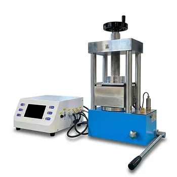
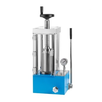
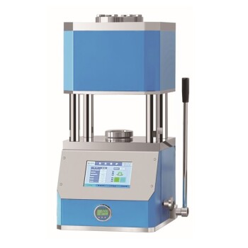
Related Products
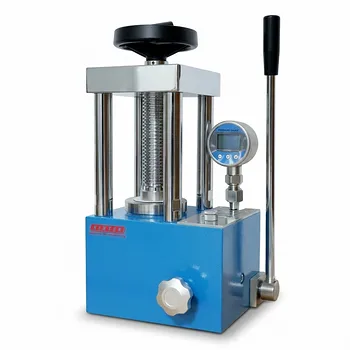
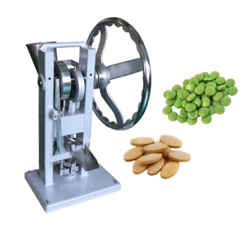
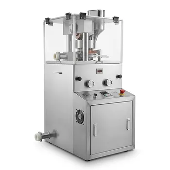
- Manual Lab Heat Press
- Manual Cold Isostatic Pressing Machine CIP Pellet Press
- kbr pellet press 2t
- Automatic Laboratory Hydraulic Press for XRF & KBR Pellet Press
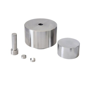
- Anti-Cracking Press Mold for Lab Use
People Also Ask
- What role does a laboratory manual hydraulic press play in the preparation of salt pellets? Ensure Research Precision
- What is a manual press? Amplify Your Force for Precision Assembly and Stamping
- How is a laboratory manual hydraulic press used in solid-state battery testing? Optimize Electrode Performance
- What is manual hydraulic press? A Guide to Simple, High-Force Compression
- Why use laboratory manual hydraulic presses for semiconductor pellets? Optimize Annealing & Crystalline Quality