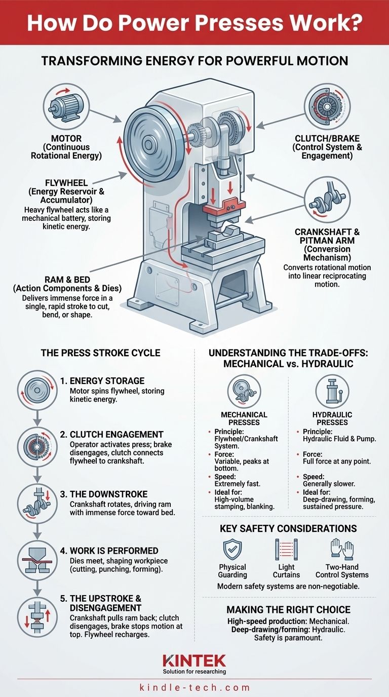
At its core, a power press is a machine that transforms energy. It takes the continuous rotational energy from a motor and converts it into a powerful, linear, up-and-down motion to cut, bend, or shape materials—most commonly sheet metal. This conversion is typically achieved through a system involving a flywheel, a clutch, and a crankshaft.
The central principle of a mechanical power press is energy accumulation and sudden release. A heavy, spinning flywheel acts like a mechanical battery, storing energy from a motor, which is then transferred through a crankshaft to deliver immense force in a single, rapid stroke.
The Key Components and Their Roles
To understand the full operational cycle, we must first understand the function of each primary component. They work together in a precise sequence to deliver force.
The Power Source (Motor)
The electric motor is the start of the entire process. Its only job is to provide the continuous rotational energy needed to spin the flywheel.
The Energy Reservoir (Flywheel)
The flywheel is a large, heavy wheel that is constantly spun by the motor. Due to its mass, it stores a significant amount of kinetic energy, which is crucial for the pressing operation itself.
The Control System (Clutch and Brake)
The clutch is the critical link that connects the spinning flywheel to the crankshaft. When engaged, it transfers the flywheel's energy to the rest of the machine. The brake works in opposition, stopping the crankshaft and ram motion precisely when the clutch is disengaged.
The Conversion Mechanism (Crankshaft)
The crankshaft, or eccentric shaft, is the heart of the machine. It functions exactly like the crankshaft in a car's engine, converting the rotational motion it receives from the flywheel into the reciprocating (up and down) motion needed for the press.
The Linkage (Pitman Arm)
The pitman arm, also known as a connecting rod, connects the rotating crankshaft to the ram. As the crankshaft turns, it pushes and pulls the pitman arm, which in turn drives the ram.
The Action Components (Ram and Bed)
The ram (or slide) is the moving part of the press that travels up and down. The upper half of the tool, or die, is mounted to it. The bed (or bolster plate) is the stationary base of the press where the lower die half is mounted.
The Press Stroke: A Step-by-Step Cycle
Understanding the individual components makes the operational cycle clear. A single press stroke is a rapid, synchronized sequence of events.
Step 1: Energy Storage
The motor runs continuously, spinning the flywheel up to its operational speed. At this stage, the flywheel is storing the kinetic energy required for the entire forming operation.
Step 2: Clutch Engagement
When the operator activates the press, the brake disengages, and the clutch engages. This instantly connects the constantly spinning flywheel to the stationary crankshaft.
Step 3: The Downstroke
The transferred energy forces the crankshaft to rotate. As it rotates from its top position, it pushes the pitman arm downwards, which in turn drives the ram with immense force toward the bed. The greatest force is available at the very bottom of this stroke.
Step 4: Work is Performed
As the ram reaches the bottom of its stroke, the upper and lower dies meet. The concentrated energy shapes the workpiece—cutting, punching, or forming it as intended.
Step 5: The Upstroke and Disengagement
The crankshaft continues its rotation, pulling the pitman arm and the ram back up to their starting position. The clutch then disengages, and the brake simultaneously engages, stopping the crankshaft and ram motion instantly at the top of the stroke. The flywheel continues to spin, recharging for the next cycle.
Understanding the Trade-offs: Mechanical vs. Hydraulic
While this describes a mechanical press, it's critical to know it's not the only type. The main alternative is the hydraulic press, which operates on a different principle.
Mechanical Presses
These are defined by the flywheel/crankshaft system. They are extremely fast and precise, making them ideal for high-volume stamping and blanking. However, their force is variable, peaking only at the very bottom of the stroke.
Hydraulic Presses
These use a large cylinder and hydraulic fluid, driven by a pump, to move the ram. They are generally slower but can deliver their full rated force at any point during the stroke. This makes them more versatile for deep-drawing or forming operations that require sustained pressure.
Key Safety Considerations
The immense forces and high speeds of power presses make them inherently dangerous. Modern safety systems are non-negotiable and include physical guarding, light curtains that stop the machine if a beam is broken, and two-hand control systems that ensure the operator's hands are clear of the die area during operation.
Making the Right Choice for Your Goal
Understanding how a press works allows you to select the right tool for the job and operate it safely.
- If your primary focus is high-speed, repeatable production (e.g., blanking coins or stamping brackets): A mechanical press is the superior choice for its speed and efficiency.
- If your primary focus is forming complex parts or deep-drawing operations (e.g., making a sink basin): A hydraulic press provides the constant, controllable tonnage required throughout the stroke.
- If your primary focus is safety and operational integrity: Understanding the clutch/brake system and the immense energy stored in the flywheel is the first step to respecting the machine and implementing proper safety protocols.
Grasping these fundamental mechanical principles is the key to effectively and safely harnessing the power of any press.
Summary Table:
| Component | Function |
|---|---|
| Motor | Provides continuous rotational energy to spin the flywheel |
| Flywheel | Heavy wheel that stores kinetic energy like a mechanical battery |
| Clutch/Brake | Engages/disengages flywheel energy; stops ram motion precisely |
| Crankshaft | Converts rotational motion into linear up-and-down motion |
| Ram & Bed | Moving and stationary parts that hold dies and perform the work |
Ready to enhance your lab or production line with precision power presses? KINTEK specializes in high-performance lab equipment and consumables, providing reliable solutions for all your metal forming and stamping needs. Whether you require the speed of a mechanical press or the versatile force of a hydraulic system, our experts are here to help you select the perfect equipment for your application. Contact us today to discuss your requirements and discover how KINTEK can optimize your operations with durable, efficient, and safe pressing solutions.
Visual Guide
Related Products
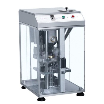
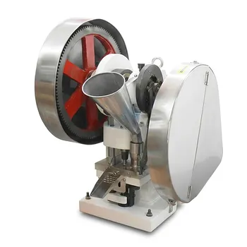
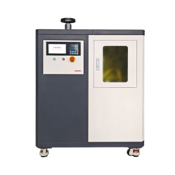
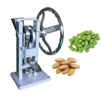
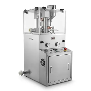
- Single Punch Electric Tablet Press Machine Laboratory Powder Tablet Punching TDP Tablet Press
- Single Punch Electric Tablet Press Machine TDP Tablet Punching Machine
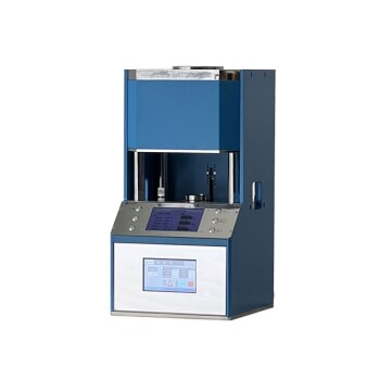
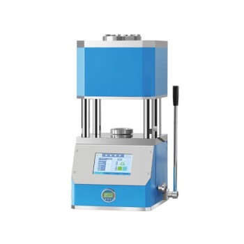
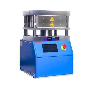
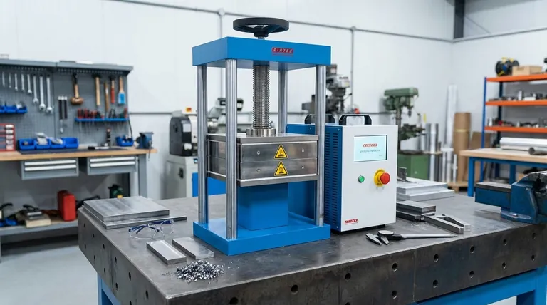
- Heated Hydraulic Press Machine with Heated Plates for Vacuum Box Laboratory Hot Press
- Automatic High Temperature Heated Hydraulic Press Machine with Heated Plates for Lab
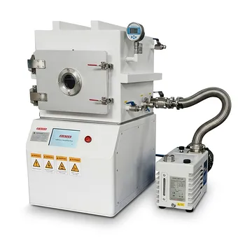
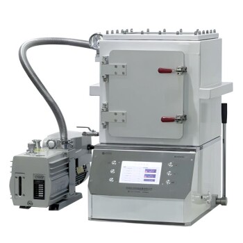
- Warm Isostatic Press for Solid State Battery Research
People Also Ask
- What is a tablet punching machine called? Choosing the Right Press for Your Production Scale
- What are advantages of single punch tablet press machine? Maximize R&D Efficiency with Minimal Material
- What is the principle of a single punch tablet press machine? A Guide to Precision Lab-Scale Production
- What are the two classifications of press machines? Single Punch vs. Rotary Presses Explained
- What is a punch tablet press? Precision Tableting for R&D and Small Batches