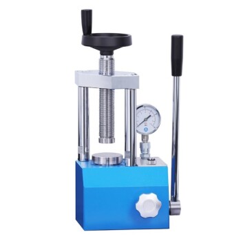
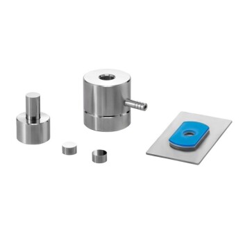
To calculate the output force of a hydraulic press, you multiply the input force by the ratio of the output piston's area to the input piston's area. This relationship is expressed in the formula F₂ = F₁ * (A₂ / A₁), where F₁ and A₁ are the force and area of the input piston, and F₂ and A₂ are the force and area of the output piston.
The core principle is that hydraulic systems don't create energy; they multiply force. This is achieved by applying a small force over a small area to generate a system-wide pressure, which then acts on a larger area to produce a proportionally larger output force.

The Principle Behind the Power: Pascal's Law
The operation of a hydraulic press is a direct application of a fundamental principle of fluid mechanics known as Pascal's Law.
What is Pascal's Law?
Pascal's Law states that a pressure change at any point in a confined, incompressible fluid is transmitted equally and undiminished throughout the entire fluid.
In a hydraulic system, this means the pressure exerted by the small input piston is the same pressure exerted on the large output piston.
Pressure as the Constant
The key to the calculation is understanding that pressure is the constant factor within the sealed system. Pressure (P) is defined as Force (F) applied over a specific Area (A), or P = F / A.
Since the pressure is the same on both sides (P₁ = P₂), we can state that F₁ / A₁ = F₂ / A₂. This simple equation is the foundation for all hydraulic force calculations.
The Role of an Incompressible Fluid
Hydraulic systems use liquids like oil because they are nearly incompressible. This property ensures that when you apply force to the input piston, the energy is efficiently transferred to creating pressure, not wasted on squeezing the fluid itself.
Calculating the Output Force: A Step-by-Step Breakdown
To find the theoretical output force, you can follow a logical sequence of calculations. Let's use the subscript 1 for the input side (small piston) and 2 for the output side (large piston).
Step 1: Determine the Input Force (F₁)
This is the force you apply to the system. For example, if you push on the input piston with 100 Newtons of force, then F₁ = 100 N.
Step 2: Calculate the Area of the Input Piston (A₁)
Most pistons are circular. The area of a circle is calculated with the formula A = πr², where r is the radius of the piston. Ensure your units are consistent (e.g., square meters).
Step 3: Calculate the System Pressure (P)
Using the values from the first two steps, calculate the pressure within the fluid using P = F₁ / A₁. The unit for pressure will be Pascals (Newtons per square meter).
Step 4: Calculate the Area of the Output Piston (A₂)
Just as with the input piston, calculate the area of the larger output piston using its radius: A₂ = πr².
Step 5: Calculate the Final Output Force (F₂)
Now, use the system pressure (P) and the area of the output piston (A₂) to find your answer. Rearranging the pressure formula gives you F₂ = P * A₂. This is the magnified force exerted by the system.
Understanding the Trade-offs: The Law of Conservation of Energy
A hydraulic press seems to create immense force from very little, but it's not magic. This force multiplication comes at a cost, governed by the law of conservation of energy.
Force vs. Distance
You cannot get more work out of a system than you put into it. The trade-off for multiplying force is distance.
To move the large output piston a small distance, you must push the small input piston a much greater distance. The ratio of distances is the inverse of the ratio of forces.
The Work Equation
In an ideal system, the work done on the input side equals the work done on the output side. Work is calculated as Work = Force × Distance.
Therefore, F₁ × d₁ = F₂ × d₂. If your output force (F₂) is 10 times the input force (F₁), the output distance (d₂) will be only 1/10th of the input distance (d₁).
Practical Limitations
The formulas above describe an ideal, frictionless system. In reality, the actual output force will be slightly lower due to energy losses from:
- Fluid Friction: Resistance within the hydraulic oil.
- Mechanical Friction: Seals and moving parts rubbing against each other.
- Leaks: Imperfect seals that can allow pressure to escape.
Making the Right Choice for Your Goal
Understanding this principle allows you to design or select a system tailored to a specific task.
- If your primary focus is maximum force multiplication: Increase the area ratio (A₂/A₁) as much as possible by using a very large output piston relative to the input piston.
- If your primary focus is the speed of the output piston: You must decrease the area ratio, which will also reduce your force advantage, as more fluid must be moved for the same distance.
- If your primary focus is efficiency: Choose a high-quality, incompressible hydraulic fluid and ensure all seals and components are in excellent condition to minimize energy losses.
By mastering the relationship between force, area, and pressure, you can precisely control and multiply force to accomplish monumental tasks.
Summary Table:
| Key Variable | Symbol | Description | Formula |
|---|---|---|---|
| Input Force | F₁ | Force applied to the small piston | User-defined |
| Input Area | A₁ | Surface area of the small piston | A₁ = πr₁² |
| Output Area | A₂ | Surface area of the large piston | A₂ = πr₂² |
| System Pressure | P | Constant pressure throughout the fluid | P = F₁ / A₁ |
| Output Force | F₂ | Magnified force exerted by the large piston | F₂ = F₁ × (A₂ / A₁) or F₂ = P × A₂ |
Need Precise Force Control in Your Laboratory?
Understanding hydraulic force is key to efficient material testing, sample preparation, and industrial processing. KINTEK specializes in providing high-quality lab equipment, including hydraulic presses and consumables, designed for accuracy and durability.
Let us help you achieve your goals:
- Maximize Force: Get the right equipment for high-pressure applications.
- Improve Efficiency: Minimize energy loss with reliable, well-sealed systems.
- Tailored Solutions: Find the perfect press for your specific lab needs and throughput.
Contact our experts today to discuss how our hydraulic presses can enhance your laboratory's capabilities and deliver the reliable performance you need.
Visual Guide

Related Products
- Automatic Laboratory Hydraulic Press for XRF & KBR Pellet Press
- Manual Lab Heat Press
- Laboratory Hydraulic Press Split Electric Lab Pellet Press
- Laboratory Manual Hydraulic Pellet Press for Lab Use
- Laboratory Hydraulic Press Lab Pellet Press Machine for Glove Box
People Also Ask
- Why is a laboratory hydraulic press used to pelletize inorganic solid electrolytes? Enhance Ionic Conductivity Testing
- What are the risks of a hydraulic press machine? Managing High-Pressure Hazards for Safer Operation
- What is the role of a laboratory hydraulic press in evaluating concrete? Test Eggshell Additive Performance
- What happens when hydraulic fluid gets too hot? The Vicious Cycle of Wear and System Failure
- What is the working of a hydraulic process? Harness Pascal's Law for Immense Force
- What is the amount of sample required when making a KBr pellet? Achieve Perfect IR Spectra with the 100:1 Ratio
- What are the maintenance required for the hydraulic system? A Proactive Guide to Prevent Costly Failures
- What is role of KBr in IR-spectroscopy? Create Transparent Pellets for Accurate Solid Sample Analysis

