At its core, calibrating a muffle furnace is not about adjusting the controller, but about verifying its accuracy. The process involves using a separate, trusted temperature measurement system to compare its reading against the temperature displayed by the furnace's controller. This comparison determines the error or offset, ensuring your work is based on the true chamber temperature, not just the setpoint.
The fundamental goal of calibration is to achieve certainty. You are moving from assuming the furnace is at the temperature you set to knowing its actual thermal performance across its working volume.
Why Furnace Calibration is Non-Negotiable
A muffle furnace's controller only knows the temperature at one specific point: the tip of its internal thermocouple. This reading can be misleading due to sensor age, electronic drift, or temperature variations within the chamber itself.
The Problem with an Uncalibrated Furnace
Without calibration, you are operating on an assumption. This can lead to failed material tests, inconsistent product quality in heat treating, or inaccurate results in ashing procedures.
Achieving Traceability and Repeatability
Calibration provides traceability, linking your furnace's performance back to a known national or international standard. This ensures that a process performed today can be accurately repeated months or years from now, regardless of equipment changes.
A Practical Guide to Calibration
While formal calibration is often performed by accredited labs, you can conduct a verification check to understand your furnace's performance. The principle remains the same: compare the furnace's display to a reliable external reference.
Step 1: Assemble Your Calibration Tools
You will need a reference thermocouple and a compatible handheld thermometer or data logger. This reference system should be more accurate than the furnace itself and, ideally, have its own recent calibration certificate.
Step 2: Prepare the Furnace
Follow standard operating procedure as a starting point. Ensure the furnace chamber is clean and empty. The furnace should be placed in a stable environment with no drafts.
Step 3: Position the Reference Thermocouple
Insert the reference thermocouple probe through the furnace door or a dedicated port. The tip of the probe should be placed as close as possible to the furnace's own internal control thermocouple. This establishes a baseline comparison.
Step 4: Perform a Stability and Uniformity Check
Set the furnace to a common operating temperature (e.g., 500 °C) and allow it to stabilize completely. This can take 30 minutes or more after the controller indicates it has reached the setpoint.
Once stable, record the furnace's displayed temperature and the reading from your external reference system. This difference is your offset at that location and temperature.
For a more thorough check, move the reference probe to other locations where you typically place samples. This helps map out the furnace's temperature uniformity, identifying potential hot or cold spots. Repeat this process at several different temperature setpoints that you use in your work.
Step 5: Analyze the Data and Take Action
You will now have a set of data comparing the setpoint to the actual temperature at various locations. If the offset is consistent, you can create a correction chart. For example, you may learn that to achieve a true 500 °C, you must set your controller to 512 °C.
Some advanced controllers allow you to program this offset directly, so the display automatically compensates for the error.
Understanding the Common Pitfalls
Accurate temperature is more complex than a single number on a display. Understanding the inherent challenges is key to mastering your process.
Thermocouple Drift and Degradation
Thermocouples are the sensors that measure temperature. They are consumable items that degrade over time, especially at high temperatures. This degradation, known as drift, almost always causes them to read lower than the actual temperature, creating a dangerous situation where the furnace is running hotter than you think.
Temperature Uniformity is a Myth
No muffle furnace chamber has a perfectly uniform temperature. Areas near the heating elements will be hotter, and the area near the door will be cooler. A Temperature Uniformity Survey (TUS) is the industrial process of mapping these variations.
Controller Reading vs. Work Zone
The controller displays the temperature at its sensor's location. The temperature your sample experiences—in the "work zone"—may be significantly different. Always calibrate for the area where your work actually happens.
Making the Right Choice for Your Goal
Your calibration needs depend entirely on your application's required level of precision and documentation.
- If your primary focus is certified compliance (e.g., aerospace, medical): You must use a third-party, accredited calibration service that provides formal, traceable documentation.
- If your primary focus is process consistency (e.g., R&D, quality control): Performing an internal verification with a high-quality reference thermometer is an effective way to control your process and correct for drift.
- If your primary focus is general heating tasks: Understanding that the setpoint is an approximation and allowing for longer soak times is often sufficient, but a periodic spot check is still highly recommended.
Ultimately, calibrating your furnace empowers you to control your process with precision and confidence.
Summary Table:
| Calibration Step | Key Action | Purpose |
|---|---|---|
| 1. Assemble Tools | Use a reference thermocouple and data logger | Compare furnace display to a trusted external reference |
| 2. Prepare Furnace | Clean chamber, ensure stable environment | Eliminate variables that affect temperature accuracy |
| 3. Position Probe | Place reference thermocouple near furnace's sensor | Establish a baseline for comparison |
| 4. Check Stability | Record temperatures after full stabilization | Determine offset and identify hot/cold spots |
| 5. Analyze Data | Create a correction chart or program offset | Compensate for error and ensure true chamber temperature |
Ensure your lab's accuracy and compliance with reliable equipment from KINTEK.
Accurate temperature control is non-negotiable for consistent results in material testing, heat treatment, and ashing procedures. KINTEK specializes in high-performance lab furnaces, calibration tools, and consumables designed for precision and durability.
Our experts can help you:
- Select the right furnace for your specific temperature and uniformity requirements
- Provide certified calibration equipment for traceable results
- Offer ongoing support to maintain your lab's peak performance
Don't leave your processes to chance. Contact our team today to discuss your application needs and ensure your furnace delivers the accuracy you depend on.
Related Products
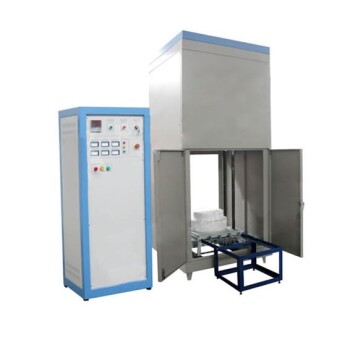
- Laboratory Muffle Oven Furnace Bottom Lifting Muffle Furnace
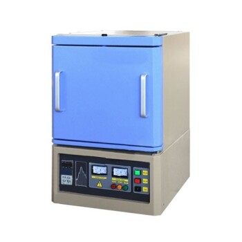
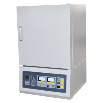
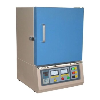
- 1800℃ Muffle Oven Furnace for Laboratory
- 1700℃ Muffle Oven Furnace for Laboratory
- 1400℃ Muffle Oven Furnace for Laboratory
- 1400℃ Laboratory Quartz Tube Furnace with Alumina Tube Tubular Furnace
People Also Ask
- What is the working temperature of a muffle furnace? Achieve Precise Heat Control for Your Lab
- What is the temperature limit on a muffle furnace? A Guide to Selecting the Right Model
- What is the high temperature of a muffle furnace? From 1100°C to 1700°C+ for Your Lab Needs
- What is the temperature range of a furnace? From 1100°C to Over 2000°C Explained
- What is the minimum temperature range for a muffle furnace? Understand Its True High-Temp Design