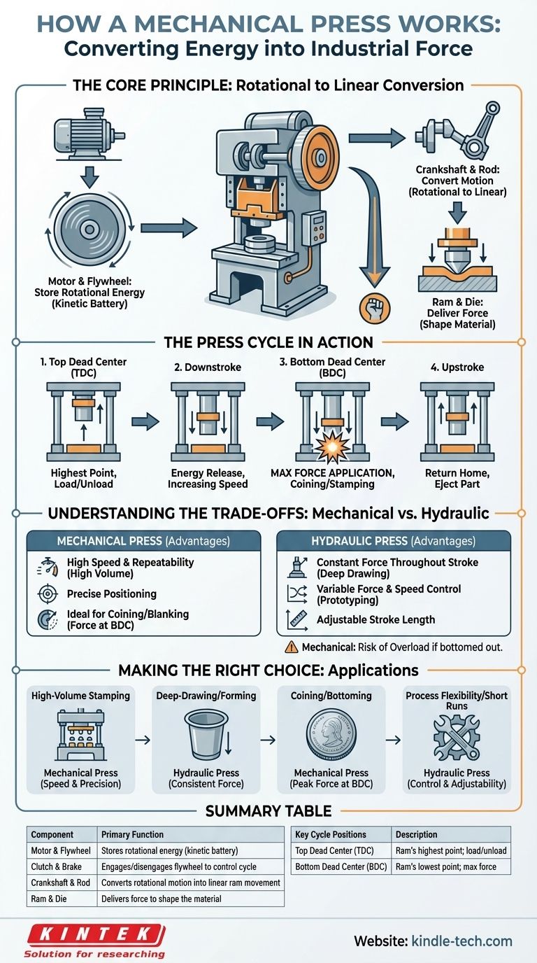
At its core, a mechanical press is a machine that translates the continuous rotational energy from a motor into a powerful, intermittent linear stroke. It achieves this by storing energy in a massive spinning flywheel and then using a crankshaft and connecting rod—much like an internal combustion engine—to drive a ram up and down, shaping material with immense force.
The central principle of a mechanical press is not the direct power of its motor, but its ability to accumulate energy over time in a heavy flywheel and release it all at once in a short, powerful punch at the bottom of its stroke.
The Core Components: From Motor to Die
To understand the operation, it's best to follow the flow of energy through the machine's key systems. Each component plays a distinct role in converting rotation into force.
The Motor and Flywheel: Storing Rotational Energy
The process begins with an electric motor. The motor's sole job is to spin a very heavy, large-diameter wheel called a flywheel.
This flywheel acts as a mechanical battery, storing kinetic energy as it spins up to a high, constant speed.
The Clutch and Brake: Controlling the Cycle
The flywheel spins continuously, but the press itself only cycles on command. This is managed by a clutch and brake system.
When the operator initiates a cycle, the clutch engages, connecting the spinning flywheel to the rest of the press's drivetrain. The brake is simultaneously disengaged, allowing the stored energy to be used. At the end of the stroke, the clutch disengages and the brake engages, stopping the ram precisely at its highest point.
The Crankshaft and Connecting Rod: Converting Motion
The energy from the engaged clutch is transferred to a crankshaft (or in some designs, an eccentric gear). This is the key mechanism for motion conversion.
A connecting rod links the crankshaft to the ram. As the crankshaft completes one 360-degree rotation, it pushes the connecting rod and the attached ram down and then pulls it back up, completing one full stroke.
The Ram and Die: Delivering the Force
The ram (also called the slide) is the component that moves vertically. The upper half of the forming tool, or die, is mounted to the ram.
The lower half of the die is fixed to the stationary press bed, known as the bolster plate. The material to be formed is placed between these two die halves.
Understanding the Press Cycle in Action
A single stroke of the press is a highly synchronized event, defined by the position of the ram.
Top Dead Center (TDC): The Starting Point
The cycle begins and ends with the ram at its highest possible position. This is known as Top Dead Center (TDC), providing maximum clearance for loading and unloading material.
The Downstroke: Energy Release
As the crankshaft rotates from 0 to 180 degrees, the ram is driven downwards. The ram's speed is highest near the middle of the stroke and decreases as it approaches the bottom.
Bottom Dead Center (BDC): Maximum Force Application
At 180 degrees of crankshaft rotation, the ram reaches its lowest point, or Bottom Dead Center (BDC).
It is at this point, as the connecting rod and crank arm straighten into an almost-vertical line, that the mechanical advantage is greatest. This is where the press delivers its maximum rated force, performing the work of coining, stamping, or forming.
The Upstroke: Returning to Home
As the crankshaft continues its rotation from 180 to 360 degrees, it pulls the ram back up towards TDC, completing the cycle. The finished part is then ejected, and the press is ready for the next cycle.
Understanding the Trade-offs: Mechanical vs. Hydraulic
The design of a mechanical press gives it a distinct set of advantages and limitations, especially when compared to its hydraulic counterpart. Understanding these trade-offs is critical for proper application.
The Speed and Repeatability Advantage
Because its stroke is fixed by a rotating crankshaft, a mechanical press is incredibly fast and consistent. It can perform many strokes per minute with a positional accuracy that is repeatable to within thousandths of an inch, making it ideal for high-volume production.
The Variable Force Limitation
A mechanical press does not deliver constant force throughout its stroke. The force is very low at the top, builds through the downstroke, and peaks just before BDC. This is a fundamental contrast to a hydraulic press, which can deliver its full rated force at any point in its stroke.
The Fixed Stroke Length
The stroke length is determined by the mechanical design of the crankshaft. It cannot be easily changed. This lack of flexibility means the press must be carefully matched to the tooling and the job.
The Risk of Overload
If a die is set too low or the wrong thickness of material is used, the press can be forced to "bottom out," generating forces far beyond its rating. This can cause catastrophic damage to the press frame or the tooling, a risk not present in the same way with pressure-limited hydraulic systems.
Making the Right Choice for Your Goal
Selecting the correct type of press depends entirely on the manufacturing task at hand. Understanding the core working principle clarifies which technology to use.
- If your primary focus is high-volume stamping or blanking: A mechanical press is the superior choice for its unmatched speed and precision repeatability.
- If your primary focus is deep-drawing or forming: A hydraulic press is often better, as its ability to apply consistent force throughout a long stroke prevents tearing the material.
- If your primary focus is coining or bottoming work: A mechanical press is ideal, as its force curve naturally delivers the immense tonnage required at the very end of the stroke.
- If your primary focus is process flexibility and variable jobs: A hydraulic press offers far more control over stroke length, speed, and pressure for prototyping or short-run applications.
Ultimately, mastering a mechanical press comes from understanding that it is a system designed to precisely control the release of stored energy.
Summary Table:
| Component | Primary Function |
|---|---|
| Motor & Flywheel | Stores rotational energy (kinetic battery) |
| Clutch & Brake | Engages/disengages the flywheel to control the cycle |
| Crankshaft & Rod | Converts rotational motion into linear ram movement |
| Ram & Die | Delivers force to shape the material placed on the bolster plate |
| Key Cycle Positions | Description |
|---|---|
| Top Dead Center (TDC) | Ram's highest point; position for loading/unloading |
| Bottom Dead Center (BDC) | Ram's lowest point; location of maximum force application |
Ready to integrate a high-speed, reliable mechanical press into your production line? At KINTEK, we specialize in providing robust lab equipment and consumables tailored to your specific manufacturing challenges. Whether your goal is high-volume stamping, precision coining, or any other metal forming application, our expertise ensures you get the right press for maximum efficiency and repeatability. Contact our experts today to discuss how our solutions can enhance your productivity and drive your success.
Visual Guide
Related Products
- Manual Lab Heat Press
- Single Punch Manual Tablet Press Machine TDP Tablet Punching Machine
- Manual Heated Hydraulic Press Machine with Heated Plates for Laboratory Hot Press
- Automatic Laboratory Heat Press Machine
- Manual Cold Isostatic Pressing Machine CIP Pellet Press
People Also Ask
- How does a laboratory hydraulic hot press ensure the quality of PHBV/natural fiber composites? Expert Guide
- Why is a laboratory hydraulic hot press essential for high-density, additive-free Silicon Carbide? Unlock Pure SiC.
- What is the function of a manual laboratory hydraulic press in electrode prep? Optimize Ohmic Contact & Stability
- What is the function of a manual laboratory hydraulic press in FT-IR? Achieve Precise Activated Carbon Sample Preparation
- How is a laboratory manual hydraulic press used in solid-state battery testing? Optimize Electrode Performance