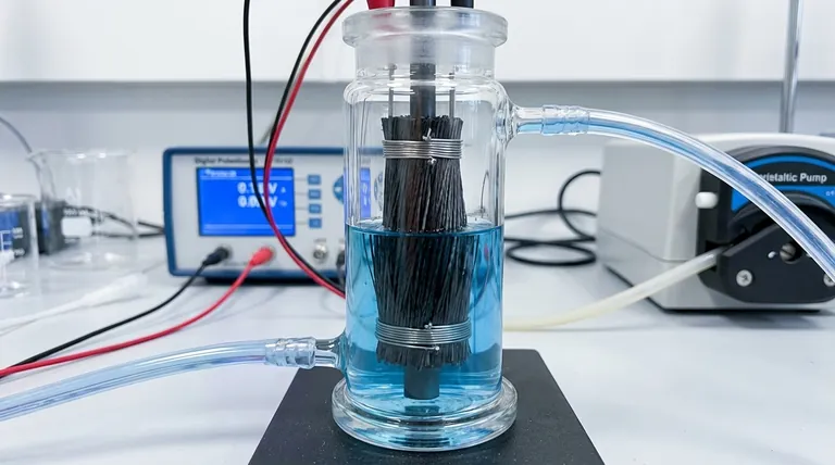
To properly install a pre-treated carbon fiber brush, you must place it within a conductive current collector, secure it firmly at both the top and bottom, and integrate it into a reactor with a specific flow path. The design must force the reactant solution to enter from a low point and exit from a high point on the opposite side, ensuring the liquid flows completely through the brush fibers.
Proper installation is not just a mechanical step; it is fundamental to the experiment's success. The goal is to create a stable three-dimensional electrode that guarantees uniform electrical contact and complete exposure of the fiber surface area to the reactant flow.
The Core Principles of Brush Installation
Before detailing the physical steps, it is critical to understand the three goals of a correct installation. Every action you take should serve to maximize these principles.
Principle 1: Electrical Conductivity
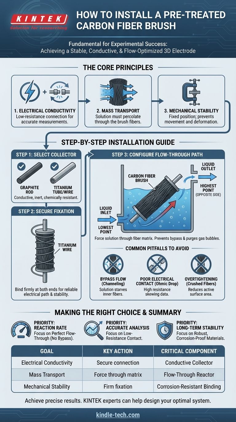
The brush acts as an electrode. A secure, low-resistance connection between the carbon fibers and the external circuit is essential for accurate measurements and efficient electrochemical reactions.
Principle 2: Mass Transport
The efficiency of your reaction depends on the reactant solution making intimate contact with the vast surface area of the carbon fibers. The setup must prevent the solution from bypassing the brush.
Principle 3: Mechanical Stability
The brush must remain in a fixed position and shape throughout the experiment. Any movement or deformation can alter the electrode's effective surface area and hydrodynamic conditions, compromising the repeatability of your results.
Step-by-Step Installation Guide
Following these steps ensures your setup adheres to the core principles and is optimized for reliable data collection.
Step 1: Select the Current Collector
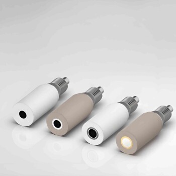
The current collector is the component that physically holds the brush and connects it to your external circuit (e.g., a potentiostat). A "suitable" collector is one that is both conductive and chemically inert in your solution.
Common choices include a graphite rod or a titanium tube/wire, as they resist corrosion and provide excellent conductivity. The collector's diameter should allow the brush to fit snugly without being overly compressed.
Step 2: Ensure Secure Fixation
The reference correctly states the brush must be securely fixed at the top and bottom. This is non-negotiable and achieves two things: it establishes a reliable electrical path and provides mechanical stability.
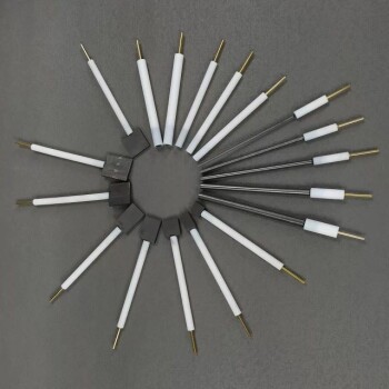
Use a corrosion-resistant conductive material, such as titanium wire, to tightly wrap and bind the ends of the carbon fiber brush to the current collector. This ensures the electrical current can flow from the collector into the fibers with minimal resistance.
Step 3: Configure the Flow-Through Path
The reactor or housing for the current collector must be engineered for a flow-through design. This is the most critical step for ensuring proper mass transport.
The liquid inlet should be at the lowest point of the chamber, and the outlet should be at the highest point on the opposite side. This configuration forces the solution to move upwards and diagonally, compelling it to percolate through the dense fiber matrix rather than flowing around it. This design also helps purge any gas bubbles that could get trapped and block the active surface area.
Understanding the Common Pitfalls
Incorrect installation is a frequent source of failed experiments. Being aware of these common mistakes will help you avoid them.
The Problem of Bypass Flow
If the brush is loose or the flow is not configured correctly, the solution will follow the path of least resistance—around the brush instead of through it. This phenomenon, known as channeling or bypass flow, starves the inner fibers of reactants and leads to drastically lower-than-expected performance.
The Risk of Poor Electrical Contact
If the connection between the brush and the collector is not tight, you create high electrical resistance. This leads to a significant voltage error known as ohmic drop, which will skew any electrochemical measurements (like cyclic voltammetry) and reduce the energy efficiency of your system.
The Danger of Overtightening
While the brush must be secure, excessive compression can be detrimental. Crushing the carbon fiber bundles can break the brittle fibers, reduce the porous volume, and impede the flow of solution through the interior of the brush, effectively lowering its active surface area.
Making the Right Choice for Your Goal
Your experimental priority will determine which aspect of the installation you should focus on most.
- If your primary focus is maximizing reaction rate: Your main concern is mass transport, so perfecting the flow-through design to eliminate all bypass flow is critical.
- If your primary focus is accurate electrochemical analysis: Your main concern is the integrity of your measurements, so achieving a stable, low-resistance electrical contact is paramount.
- If your primary focus is long-term operational stability: Your main concern is durability, so you must use robust, corrosion-proof materials for the fixation and collector.
By treating the installation as a critical variable of the experiment itself, you ensure the integrity and reliability of your results.
Summary Table:
| Installation Goal | Key Action | Critical Component |
|---|---|---|
| Electrical Conductivity | Secure, low-resistance connection | Conductive current collector (e.g., graphite, titanium) |
| Mass Transport | Force solution through fiber matrix | Flow-through reactor design (bottom inlet, top outlet) |
| Mechanical Stability | Firm fixation at top and bottom | Corrosion-resistant binding (e.g., titanium wire) |
Achieve precise and repeatable results in your electrochemical experiments. Proper electrode installation is fundamental to data integrity. KINTEK specializes in high-quality lab equipment and consumables, including components for custom reactor setups. Our experts can help you select the right materials and design a system that ensures optimal performance for your specific application.
Contact our team today to discuss your laboratory needs and how we can support your research success.
Visual Guide
Related Products
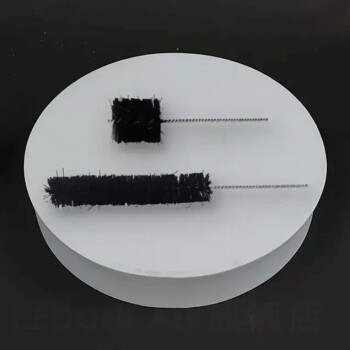
- Conductive Carbon Fiber Brush for Static Removal and Cleaning
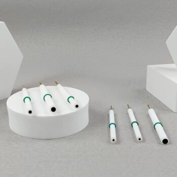
- CF KF Flange Vacuum Electrode Feedthrough Lead Sealing Assembly for Vacuum Systems
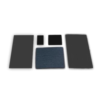
- Conductive Carbon Cloth Carbon Paper Carbon Felt for Electrodes and Batteries
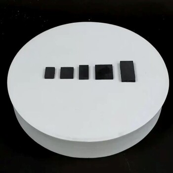
- Glassy Carbon Electrochemical Electrode
- Glassy Carbon Sheet RVC for Electrochemical Experiments
People Also Ask
- What is the recommended cleaning procedure for a carbon fiber brush after use? Extend Brush Life and Maintain Performance
- What parameters require monitoring during an experiment involving a carbon fiber brush? Ensure Reliable Results
- What types of chemical substances should a carbon fiber brush avoid contact with? Protect Your Precision Tool from Damage
- Is a carbon brush a good conductor of electricity? The Surprising Engineering Choice
- What environmental conditions should be avoided when operating or storing a carbon fiber brush? Protect Your Investment from Damage