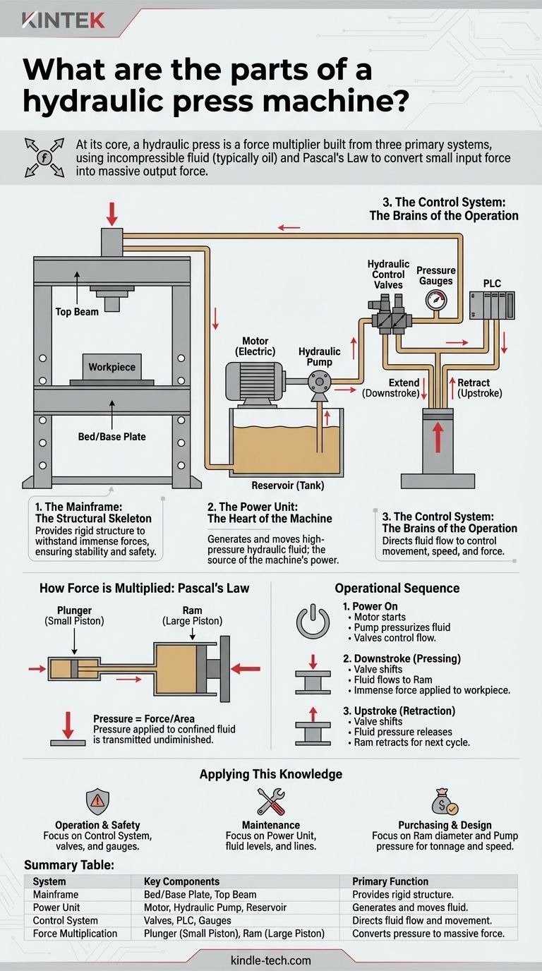
At its core, a hydraulic press is built from three primary systems: a structural mainframe, a hydraulic power and control system, and the cylinders that convert fluid pressure into mechanical force. These components work in unison, leveraging an incompressible fluid (typically oil) to multiply a small initial force into a much larger output force.
A hydraulic press does not create energy; it is a force multiplier. Understanding that a small force applied to a small area generates a pressure that, when applied to a large area, results in a massive output force is the key to grasping how all its individual parts function as a cohesive whole.
The Foundational Systems of a Hydraulic Press
A hydraulic press isn't just a random collection of parts. It's best understood as three distinct but interconnected systems, each with a critical role.
1. The Mainframe: The Structural Skeleton
The mainframe provides the rigid structure necessary to withstand the immense forces generated by the press. It anchors all other components and ensures stability and safety during operation.
This structure is typically made of high-strength steel and includes a bed or base plate where the workpiece is placed and a top beam that houses or supports the main cylinder.
2. The Power Unit: The Heart of the Machine
The power unit is responsible for creating and moving the high-pressure hydraulic fluid that drives the machine. It is the source of the machine's power.
This system includes a motor (usually electric) that drives a hydraulic pump. The pump draws fluid from a reservoir (tank) and pushes it into the hydraulic circuit under pressure.
3. The Control System: The Brains of the Operation
The control system directs the flow of hydraulic fluid, allowing the operator to manage the press's movement, speed, and force.
Key elements are the hydraulic control valves. These valves open and close to direct fluid to either extend (downstroke) or retract (upstroke) the main piston. This system also includes pressure gauges, switches, and often a programmable logic controller (PLC) for automated cycles.
How Force is Multiplied: The Core Hydraulic Components
The "magic" of a hydraulic press happens within its core hydraulic components, which operate based on Pascal's Law.
The Principle of Operation: Pascal's Law
Pascal's Law states that pressure applied to a confined fluid is transmitted undiminished throughout the fluid. By using two pistons of different sizes, this principle allows for force multiplication.
The Plunger (Small Piston)
In many designs, a small piston, often called the plunger, is where the initial pressure is generated. The pump forces fluid into this smaller cylinder.
Because the area of this piston is small, even a moderate amount of fluid pressure results in a specific force value (Force = Pressure x Area).
The Ram (Large Piston)
The pressurized fluid from the small cylinder flows into a much larger cylinder, which houses a large piston called the ram. This is the component that moves down to press the workpiece.
Since the pressure is the same but the area of the ram is much larger, the resulting output force is proportionally greater. A ram with 10 times the surface area of the plunger will produce 10 times the force.
Hydraulic Fluid and Lines
The hydraulic fluid (usually a specialized oil) is the lifeblood of the system. It must be incompressible to transfer pressure efficiently. This fluid is transported between the pump, valves, and cylinders through a network of high-pressure pipes and hoses.
Understanding the Operational Sequence
Seeing how the parts interact in a typical cycle makes their individual functions clear.
Step 1: Power On and Pressurization
The electric motor starts, driving the hydraulic pump. The pump begins moving fluid, building up pressure within the hydraulic circuit, which is held in check by the control valves.
Step 2: The Downstroke (Pressing)
When the operator activates the press, a directional control valve shifts. This opens a path for the high-pressure fluid to flow into the main cylinder, above the ram.
The immense pressure acts on the large surface area of the ram, forcing it downward with tremendous force onto the workpiece.
Step 3: The Upstroke (Retraction)
After the pressing operation is complete, the control valve shifts again. It directs fluid to the other side of the ram (the bottom side) or simply opens a path for the fluid above the ram to return to the reservoir.
This releases the pressure, and often a smaller, secondary mechanism or gravity helps retract the ram back to its starting position, ready for the next cycle.
Applying This Knowledge
Understanding these components helps you assess a machine's capabilities and requirements.
- If your primary focus is operation or safety: Your attention should be on the control system. Understand what each valve, button, and gauge does to ensure you are always in command of the machine's immense power.
- If your primary focus is maintenance: The power unit and hydraulic lines are your key areas. Regularly check fluid levels, look for leaks in hoses, and listen to the pump and motor to catch issues early.
- If your primary focus is purchasing or design: The specifications of the ram (diameter) and the power unit (pressure rating) are paramount, as their relationship dictates the machine's maximum force (tonnage) and operating speed.
By understanding how each part contributes to the system, you can operate, maintain, and evaluate any hydraulic press with confidence.
Summary Table:
| System | Key Components | Primary Function |
|---|---|---|
| Mainframe | Bed/Base Plate, Top Beam | Provides rigid structure to withstand force |
| Power Unit | Motor, Hydraulic Pump, Reservoir | Generates and moves high-pressure hydraulic fluid |
| Control System | Valves, PLC, Gauges | Directs fluid flow to control movement, speed, and force |
| Force Multiplication | Plunger (Small Piston), Ram (Large Piston) | Converts fluid pressure into massive mechanical force |
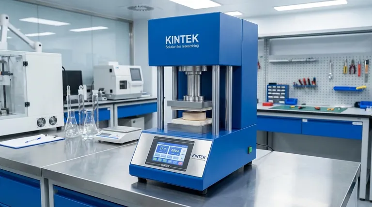
Need a reliable hydraulic press or expert advice on lab equipment?
KINTEK specializes in high-performance lab equipment and consumables, serving the precise needs of laboratories and industrial facilities. Whether you're setting up a new production line or require maintenance support for your existing hydraulic systems, our expertise ensures you get the right solution for maximum efficiency and safety.
Contact our specialists today to discuss your specific requirements and discover how KINTEK can support your operations.
Visual Guide
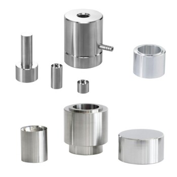
Related Products
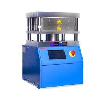
- Heated Hydraulic Press Machine with Heated Plates for Vacuum Box Laboratory Hot Press
- Automatic High Temperature Heated Hydraulic Press Machine with Heated Plates for Lab
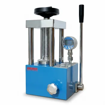
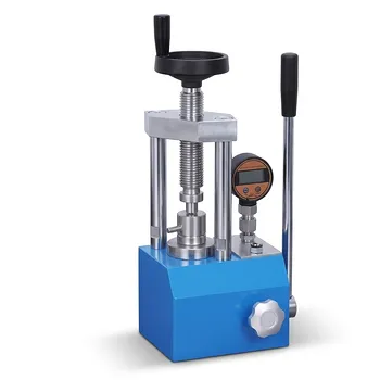
- Manual High Temperature Heated Hydraulic Press Machine with Heated Plates for Lab
- Heated Hydraulic Press Machine with Integrated Manual Heated Plates for Lab Use
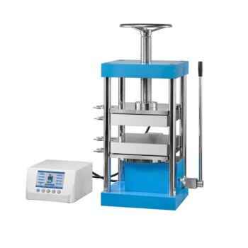
- 24T 30T 60T Heated Hydraulic Press Machine with Heated Plates for Laboratory Hot Press
People Also Ask
- What are heated hydraulic presses used for? Molding Composites, Vulcanizing Rubber, and More
- What does a hydraulic heat press do? Achieve Industrial-Scale, Consistent Pressure for High-Volume Production
- What role does a heated hydraulic press play in Cold Sintering (CSP)? Enhancing LATP-Halide Densification
- What is the core function of a laboratory heated hydraulic press in CSP? Revolutionize Low-Temp Ceramic Sintering
- Why is a heated laboratory hydraulic press necessary for composite laminates? Achieve Void-Free Structural Integrity