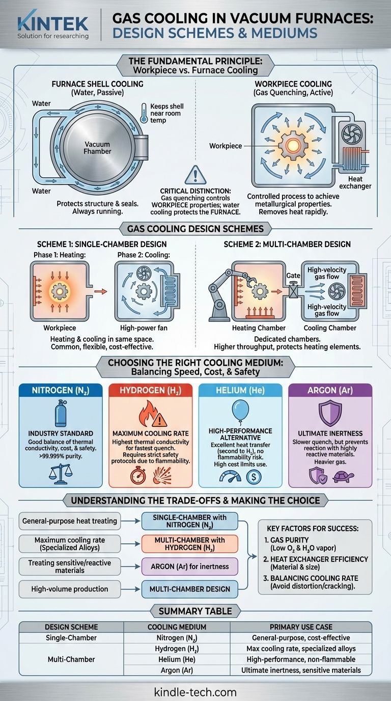
At its core, gas cooling in a vacuum furnace utilizes two primary design schemes and a select group of gases. The designs either perform heating and cooling in the same chamber or in separate, dedicated chambers. The most common cooling medium is high-purity nitrogen, though hydrogen, helium, and argon are used for specific applications demanding different cooling rates or levels of inertness.
The critical distinction to understand is that gas cooling (or "gas quenching") is an active process to control the properties of the workpiece, while a separate water-cooling system is always running to protect the furnace structure itself.
The Fundamental Principle: Workpiece vs. Furnace Cooling
To operate a vacuum furnace correctly, it's essential to differentiate between the two cooling systems at play. They serve entirely different purposes.
Cooling the Furnace Shell (The "Cold Wall")
A vacuum furnace is built with a "cold wall" construction. This is typically a double-skinned shell where cooling water circulates continuously.
This system's only job is to protect the furnace. It keeps the outer shell near room temperature, prevents structural components from deforming under heat, and ensures the vacuum seals remain intact and effective.
Cooling the Workpiece (Gas Quenching)
Gas quenching is a controlled, active step in the heat-treatment process. After the workpiece is heated in a vacuum, a high-purity gas is introduced and rapidly circulated.
This process removes heat from the workpiece at a specific, controlled rate to achieve the desired metallurgical properties, such as hardness. This is entirely separate from the furnace's own water-cooling jacket.
Gas Cooling Design Schemes
The physical layout of the furnace dictates how the gas quenching process is performed.
Scheme 1: Single-Chamber Design
In this common configuration, both the heating and cooling cycles occur in the same space.
After the heating phase, the heating elements are turned off, and the quenching gas is forced into the chamber. A high-power fan circulates the gas through the hot workload and then over an internal heat exchanger to remove the heat.
Scheme 2: Multi-Chamber Design
In a multi-chamber furnace, the workpiece is physically moved from the heating chamber to a separate, dedicated cooling chamber.
This design isolates the delicate heating elements from the high-velocity, turbulent gas flow of the quench. It also allows for higher production throughput, as one load can be cooled while the next is being heated.
Choosing the Right Cooling Medium
The choice of gas is determined by the required cooling speed, material compatibility, cost, and safety considerations.
Nitrogen (N₂): The Industry Standard
High-purity nitrogen (typically >99.999%) is the most widely used quenching gas. It offers a good balance of thermal conductivity, cost-effectiveness, and safety, as it is relatively inert.
Hydrogen (H₂): For Maximum Cooling Rate
Hydrogen has exceptionally high thermal conductivity, making it the most effective gas for achieving the fastest possible cooling rates. However, its flammability requires extensive safety systems and specialized furnace construction.
Helium (He): The High-Performance Alternative
Helium offers excellent heat transfer properties, second only to hydrogen, without the associated safety risks. Its high cost, however, limits its use to very specific and critical applications.
Argon (Ar): For Ultimate Inertness
Argon is heavier and has lower thermal conductivity than nitrogen, resulting in a slower quench. It is chosen when treating highly reactive materials that could have a slight reaction even with high-purity nitrogen.
Understanding the Trade-offs
Effective gas quenching is not just about speed; it's about control and precision. Several factors must be balanced to achieve the desired outcome without damaging the part.
The Imperative of Gas Purity
To maintain the bright, clean surface finish expected from vacuum heat-treating, the quenching gas must be extremely pure.
Impurities like oxygen (target < 2 ppm) and water vapor (target < 5-10 ppm) can cause surface oxidation during the cooling phase, defeating a primary benefit of using a vacuum furnace.
The Role of the Heat Exchanger
The efficiency of the cooling process is heavily dependent on the heat exchanger. Its size and material—often steel, stainless steel, or copper for maximum thermal transfer—are critical factors determining how quickly heat can be removed from the circulating gas.
Balancing Cooling Rate and Distortion
While a rapid quench is often desired for hardness, cooling a part too quickly can induce thermal stress. This can lead to distortion or even cracking, especially in components with complex geometries or varying cross-sections. The cooling rate must be carefully matched to the material and part design.
Making the Right Choice for Your Goal
Your selection of a cooling scheme and medium should be driven directly by your process requirements and primary objectives.
- If your primary focus is general-purpose heat treating: A single-chamber furnace using high-purity nitrogen is the most common, flexible, and cost-effective solution.
- If your primary focus is maximum cooling rate for specialized alloys: Hydrogen is the superior medium, but it mandates a furnace designed with rigorous safety protocols.
- If your primary focus is treating highly sensitive or reactive materials: Argon provides the most inert environment, accepting a slower cooling rate as a trade-off.
- If your primary focus is high-volume production: A multi-chamber design offers the best throughput by separating the heating and cooling stages.
By understanding these core components and principles, you can ensure the furnace's gas cooling capabilities align perfectly with your material's specific metallurgical needs.
Summary Table:
| Design Scheme | Cooling Medium | Primary Use Case |
|---|---|---|
| Single-Chamber | Nitrogen (N₂) | General-purpose heat treating, cost-effective |
| Multi-Chamber | Hydrogen (H₂) | Maximum cooling rate for specialized alloys |
| - | Helium (He) | High-performance cooling without flammability risk |
| - | Argon (Ar) | Ultimate inertness for sensitive/reactive materials |
Ready to select the ideal gas cooling system for your laboratory's vacuum furnace? The right combination of design and quenching medium is critical for achieving precise metallurgical properties and maximizing throughput. KINTEK specializes in lab equipment and consumables, serving laboratory needs. Our experts can help you choose a furnace configuration that ensures optimal cooling rates, material integrity, and process efficiency. Contact us today to discuss your specific application and get a tailored solution!
Visual Guide
Related Products
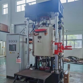
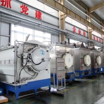
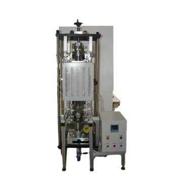
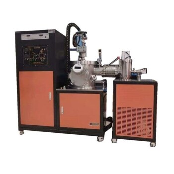
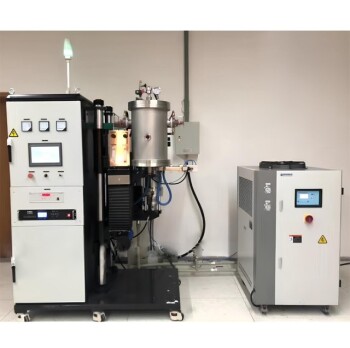
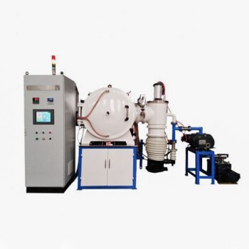
- Vacuum Heat Treat and Pressure Sintering Furnace for High Temperature Applications
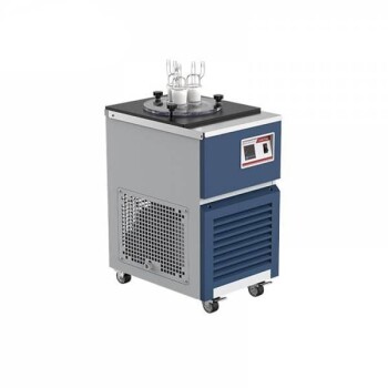
- Vacuum Cold Trap Chiller Indirect Cold Trap Chiller
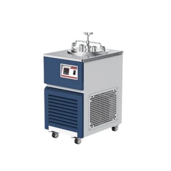
- Vacuum Cold Trap Direct Cold Trap Chiller
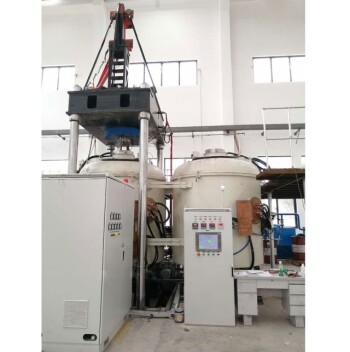
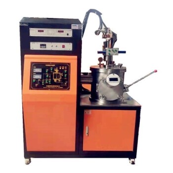
- 600T Vacuum Induction Hot Press Furnace for Heat Treat and Sintering
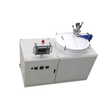
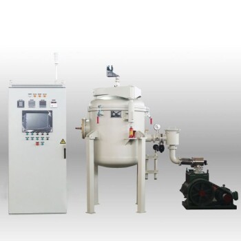
- Vacuum Heat Treat Sintering Brazing Furnace
People Also Ask
- How does a high-temperature vacuum sintering furnace contribute to the formation of Fe-Cr-Al porous materials?
- How does a high-temperature vacuum sintering furnace facilitate the post-treatment of Zirconia coatings?
- Why is it necessary to use sintering aids for PLS? Achieve Full Density in Ultra-High Temperature Ceramics
- What critical process conditions does a vacuum sintering furnace provide for titanium? Expert Diffusion Bonding Guide
- What is a high temperature vacuum sintering furnace? Achieve Maximum Purity and Material Density