While induction soldering offers unparalleled speed and precision for specific tasks, it is far from a universal solution. Its primary disadvantages are the significant initial capital investment for equipment, the complex engineering required to design and fabricate custom heating coils for each specific joint, the inherent risk of overheating sensitive nearby components, and its general unsuitability for low-volume or high-mix production environments.
Induction soldering trades the flexibility and low entry cost of manual methods for extreme efficiency within a highly specific, repeatable process. Its disadvantages all stem from the high upfront investment in capital and engineering required to perfect that single process, making it impractical for varied or small-scale work.
The Financial Barrier: High Initial Investment
The most immediate disadvantage of adopting induction soldering is the cost. This barrier goes beyond the price of the main unit and represents a significant strategic investment.
The Cost of the Power Supply
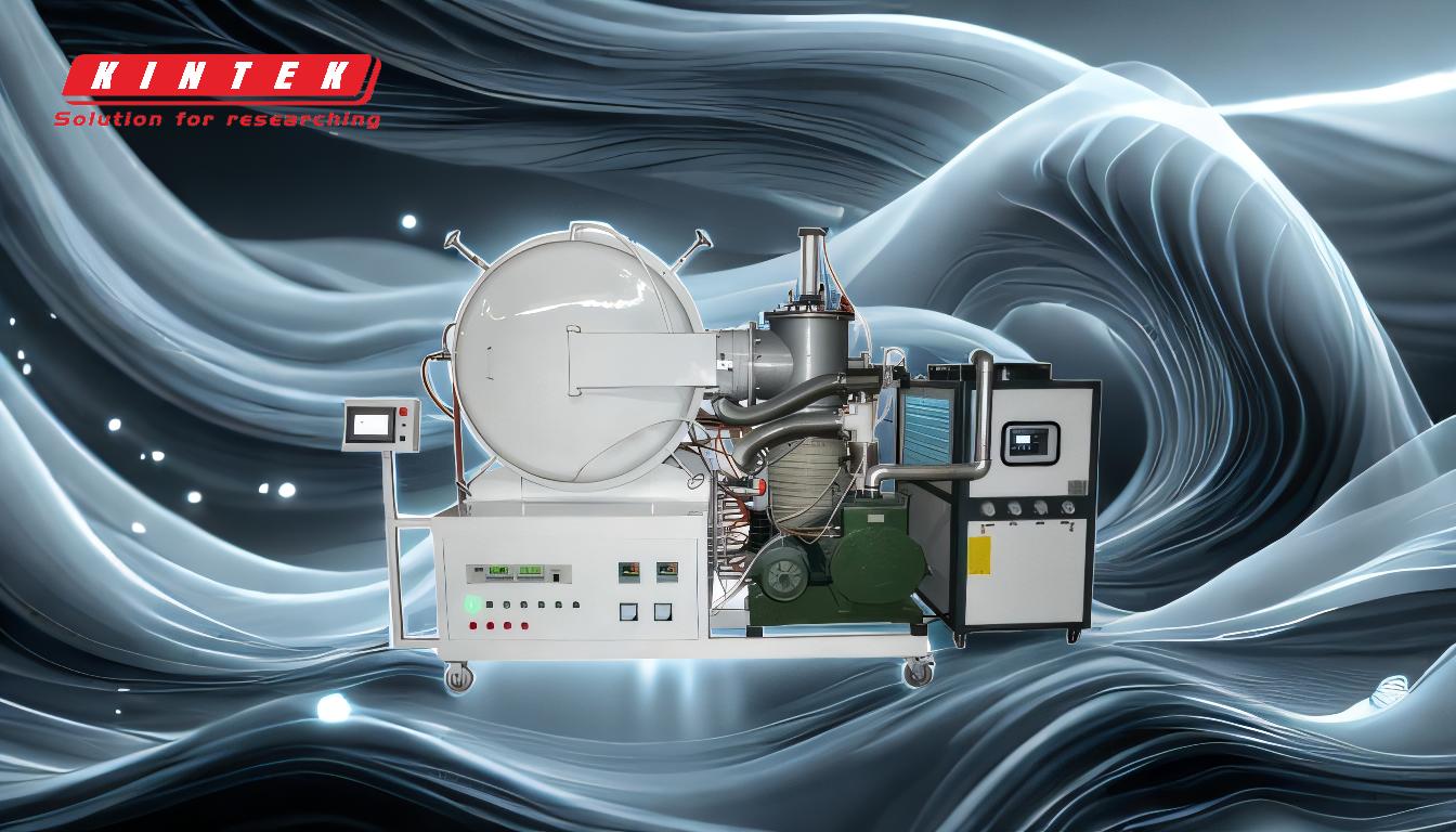
An induction heating system is a piece of industrial equipment, not a simple benchtop tool. The power supply alone can cost thousands to tens of thousands of dollars, depending on its power output and control features. This initial outlay is orders of magnitude higher than that for professional-grade soldering irons or hot air stations.
The Hidden Cost of Coil Development
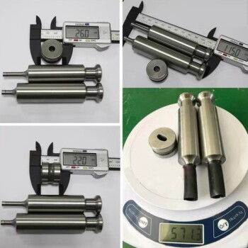
Unlike a soldering iron tip, an induction coil is not a universal, off-the-shelf part. Each new joint geometry requires a custom-designed and fabricated coil to ensure the magnetic field is precisely focused on the target area. This process involves significant engineering, prototyping, and testing, adding recurring development costs for each new product you introduce.
The Engineering Challenge: Geometry and Material Sensitivity
Induction heating is a science of proximity and material properties. This precision is a strength but also a source of major limitations, creating significant engineering hurdles.
Why One Coil Does Not Fit All
The shape, size, and proximity of the induction coil dictates the heating pattern. A coil designed to solder a wire to a large brass terminal is completely ineffective for soldering a small connector pin. This dependency means that even minor changes in a part's design can require a complete redesign of the heating coil and process parameters.
Heating Complex or Dissimilar Materials
Induction works by inducing electrical currents within the part itself. If you are soldering two parts with different masses or material compositions (e.g., a thin copper wire to a thick steel lug), they will heat at vastly different rates. This requires careful power pulsing and coil design to avoid melting the smaller component before the larger one even reaches soldering temperature.
The Proximity Requirement
For efficient heating, the induction coil must be placed very close to the workpiece, often within millimeters. In many complex assemblies or tight enclosures, there simply isn't enough physical space to position a coil correctly, making the method impossible without a product redesign.
Understanding the Trade-offs: Speed vs. Control
The defining advantage of induction—its speed—is also the source of its most critical operational trade-off. Rapid heating can easily lead to a loss of control and damage to the product.
The Risk of Overheating Sensitive Components
The intense, high-frequency energy can easily damage nearby components that are not the primary target. Plastic housings can melt, insulation on adjacent wires can be compromised, and sensitive electronic components on a PCB can be destroyed by the rapidly expanding heat zone. This risk of collateral damage is a primary concern.
The Myth of "Instant" Setup
While an individual heating cycle may last only a few seconds, the time required to develop a stable, repeatable process can take days or weeks. This development cycle involves dialing in the power, frequency, heating time, and coil position to achieve a perfect solder joint without causing damage, a far cry from the "plug-and-play" nature of a soldering iron.
Limited Use for Standard PCB Assembly
Induction is generally a poor choice for soldering traditional through-hole or fine-pitch surface-mount components on a printed circuit board. The magnetic field cannot be localized enough to heat a single pin without also heating adjacent pins, traces, and ground planes, leading to unintended solder reflow and component damage.
Is Induction Soldering the Wrong Choice for You?
Choosing the right soldering method depends entirely on your operational goals, production volume, and the nature of the parts being joined.
- If your primary focus is prototyping, repair, or R&D: The high setup cost and lack of flexibility make induction a poor fit; manual soldering irons or hot air are superior.
- If your primary focus is high-mix, low-volume production: The recurring engineering cost and time required for custom coil design make induction economically unviable.
- If your assemblies are complex, dense, or contain many heat-sensitive materials: The risk of collateral heat damage from induction may be too high without an expensive and time-consuming process development phase.
- If your primary focus is high-volume, repeatable manufacturing of a specific joint: The disadvantages are likely outweighed by its immense speed, consistency, and potential for automation, making it an excellent choice.
Understanding these limitations is the first step toward making an informed decision, ensuring you select the technology that best serves your specific manufacturing needs.
Summary Table:
| Disadvantage | Key Impact |
|---|---|
| High Initial Investment | Significant capital cost for power supply and equipment. |
| Custom Coil Design | Requires engineering time and cost for each unique joint geometry. |
| Risk of Overheating | Can damage nearby sensitive components and materials. |
| Limited Flexibility | Unsuitable for low-volume, high-mix, or prototyping work. |
Struggling to choose the right soldering technology for your lab's specific needs? KINTEK specializes in lab equipment and consumables, providing expert guidance to help you select the most efficient and cost-effective solutions for your production environment. Let our expertise in laboratory needs ensure you avoid costly mistakes and optimize your processes. Contact us today for a personalized consultation!
Related Products
- Chemical Vapor Deposition CVD Equipment System Chamber Slide PECVD Tube Furnace with Liquid Gasifier PECVD Machine
- Manual Cold Isostatic Pressing Machine CIP Pellet Press
- Rotating Disk Electrode and Rotating Ring Disk Electrode (RRDE)
- Single Punch Tablet Press Machine and Mass Production Rotary Tablet Punching Machine for TDP
- RF PECVD System Radio Frequency Plasma-Enhanced Chemical Vapor Deposition RF PECVD
People Also Ask
- How are PECVD and CVD different? A Guide to Choosing the Right Thin-Film Deposition Process
- What are the benefits of plasma enhanced CVD? Achieve High-Quality, Low-Temperature Film Deposition
- What is the difference between CVD and PECVD? Choose the Right Thin-Film Deposition Method
- What is the difference between thermal CVD and PECVD? Choose the Right Thin-Film Deposition Method
- What is the PECVD process? Achieve Low-Temperature, High-Quality Thin Film Deposition