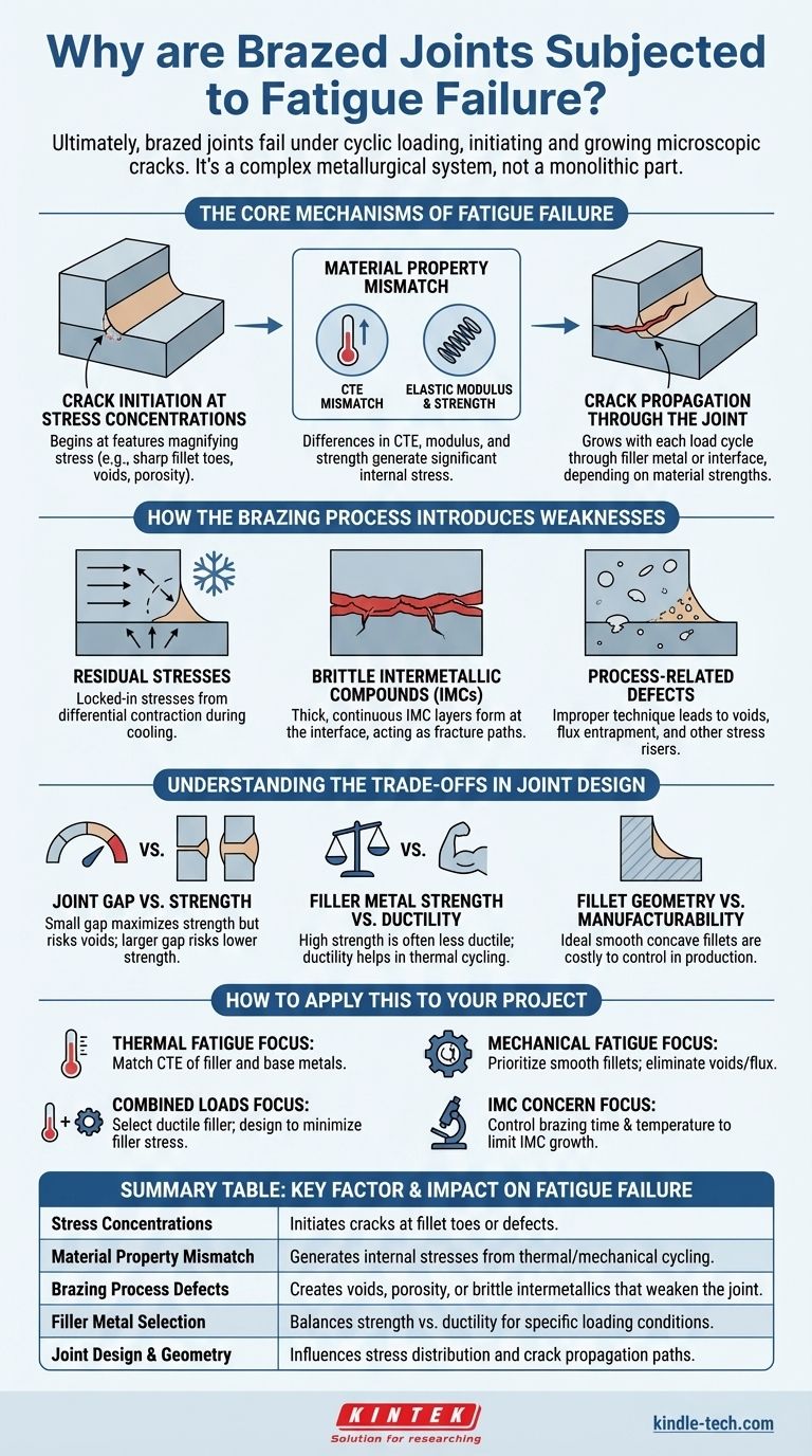
Ultimately, brazed joints fail under fatigue for the same fundamental reason as any other metallic structure: the repeated application of stress, known as cyclic loading, initiates and grows microscopic cracks until the joint can no longer support the load. These failures are rarely caused by a single flaw, but by a combination of factors including stress concentrations at the joint's geometry, mismatches in material properties, and defects introduced during the brazing process itself.
The core issue is that a brazed joint is a metallurgical system, not a monolithic part. Fatigue failure is driven by the complex interactions at the interface between two different base metals and a filler metal, each with unique mechanical and thermal properties.
The Core Mechanisms of Fatigue Failure
A fatigue failure in a brazed joint unfolds in two stages: crack initiation and propagation. Understanding where and why these cracks start is the key to preventing them.
Crack Initiation at Stress Concentrations
Nearly all fatigue cracks begin at a stress concentration, which is a geometric feature that locally magnifies the applied stress. In a brazed joint, these are unavoidable.
The most common initiation site is the braze fillet toe, which is the point where the filler metal meets the surface of the base material. A sharp or concave fillet acts like a microscopic notch, concentrating stress from vibration or thermal expansion.
Other initiation sites include internal defects like voids, porosity, or flux inclusions. These act as internal notches, creating high-stress regions deep within the joint where cracks can easily form.
The Role of Material Property Mismatch
A brazed joint connects at least two materials—the base metal(s) and the filler alloy. Their properties are never identical, and this mismatch is a primary driver of fatigue.
The most critical mismatch is often the Coefficient of Thermal Expansion (CTE). When the joint is heated and cooled (thermal cycling), materials with different CTEs expand and contract at different rates. This generates significant internal stress, especially at the interface, even with no external load.
Differences in elastic modulus and strength also contribute. A more flexible filler metal may deform more than the rigid base metal, creating strain concentrations at the interface that fuel the fatigue process.
Crack Propagation Through the Joint
Once a crack initiates, it will grow with each load cycle. The path it takes depends on the relative strengths of the materials involved.
A crack may propagate directly through the filler metal, especially if the filler is significantly weaker or more brittle than the base metal. Alternatively, it can travel along the interface between the filler and base metal if the bond is poor or if brittle intermetallic compounds have formed there.
How the Brazing Process Can Introduce Weaknesses
The ideal brazed joint is perfectly uniform, but the reality of the heating and cooling process introduces inherent features that can become weak points.
Residual Stresses
As the brazed assembly cools from the brazing temperature, the different materials contract at different rates. This locks residual stress into the joint. These built-in stresses can be substantial and reduce the amount of additional cyclic stress the joint can withstand before a fatigue crack initiates.
Brittle Intermetallic Compounds (IMCs)
During brazing, some of the base metal dissolves into the liquid filler metal. Upon cooling, this can form new, distinct layers of intermetallic compounds (IMCs) at the interface.
While a thin, well-dispersed IMC layer is essential for a good metallurgical bond, thick or continuous IMC layers are often extremely brittle. These act as a pre-existing fracture path, dramatically reducing the joint's resistance to fatigue crack growth.
Process-Related Defects
Improper brazing technique is a direct cause of fatigue-prone defects. Insufficient filler metal creates voids, while improper joint cleaning can lead to flux entrapment. Both act as significant internal stress risers, providing ideal locations for fatigue cracks to begin.
Understanding the Trade-offs in Joint Design
Designing a fatigue-resistant brazed joint involves balancing competing factors. There is no single "best" design, only the best design for a specific application.
Joint Gap vs. Strength
A very small joint gap can maximize the strength of the joint through capillary action but makes it difficult for gas or flux to escape, increasing the risk of voids. A larger gap reduces this risk but may result in a lower-strength joint with more filler metal, which can be a problem if the filler is the "weak link" in the system.
Filler Metal Strength vs. Ductility
A high-strength filler metal might seem ideal, but these alloys are often less ductile (more brittle). A more ductile filler can better accommodate strain from thermal mismatches by deforming slightly, which can improve fatigue life in thermal cycling applications. However, this same ductility may be a disadvantage under high mechanical loads.
Fillet Geometry vs. Manufacturability
A large, smooth, and concave fillet is ideal for reducing stress concentration and improving fatigue life. However, achieving this perfect geometry can be difficult and costly to control in a production environment, requiring more filler metal and precise process control.
How to Apply This to Your Project
Your design strategy must be guided by the dominant type of fatigue the joint will experience.
- If your primary focus is thermal fatigue resistance: Choose a filler metal and base metal combination with closely matched Coefficients of Thermal Expansion (CTE).
- If your primary focus is mechanical fatigue resistance: Prioritize a joint design with smooth, generous fillets and implement strict process controls to eliminate internal voids and flux inclusions.
- If your joint will see both thermal and mechanical loads: Select a ductile filler metal that can absorb thermal strains while designing the joint geometry (e.g., a lap joint) to minimize the stress carried by the filler metal itself.
- If intermetallic brittleness is a concern: Control your brazing time and temperature meticulously to limit the growth of IMC layers at the interface.
By understanding that a brazed joint is a complex system, you can move beyond simply joining parts and begin engineering robust, reliable connections that last.
Summary Table:
| Key Factor | Impact on Fatigue Failure |
|---|---|
| Stress Concentrations | Initiates cracks at fillet toes or defects |
| Material Property Mismatch (CTE/Modulus) | Generates internal stresses from thermal/mechanical cycling |
| Brazing Process Defects | Creates voids, porosity, or brittle intermetallics that weaken the joint |
| Filler Metal Selection | Balances strength vs. ductility for specific loading conditions |
| Joint Design & Geometry | Influences stress distribution and crack propagation paths |
Engineer fatigue-resistant brazed joints with confidence. At KINTEK, we specialize in providing advanced brazing solutions and lab equipment to help you optimize joint design, select the right materials, and implement precise process controls. Whether you're dealing with thermal cycling, mechanical loads, or complex material combinations, our expertise ensures your brazed connections meet the highest standards of durability and performance. Contact our experts today to discuss how we can support your specific application needs with tailored solutions and reliable equipment.
Visual Guide
Related Products
- Vacuum Hot Press Furnace Machine Heated Vacuum Press
- Vacuum Hot Press Furnace Heated Vacuum Press Machine Tube Furnace
- 600T Vacuum Induction Hot Press Furnace for Heat Treat and Sintering
- Vacuum Hot Press Furnace Machine for Lamination and Heating
- Vacuum Heat Treat Furnace with Ceramic Fiber Liner
People Also Ask
- What is the effect of increasing the pressure during sintering hot press sintering? Optimize Density, Time, and Temperature
- What is the main function of hot press forming? Achieve Superior Strength & Precision in Manufacturing
- What is the hot pressing method of sintering? A Guide to High-Density Material Fabrication
- What is pressure-assisted sintering? Achieve Denser, Stronger Materials Faster
- Why is pressing force important in sintering? Achieve Denser, Stronger Materials Faster