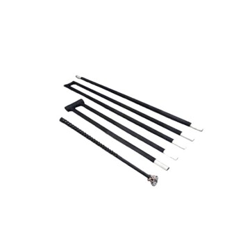
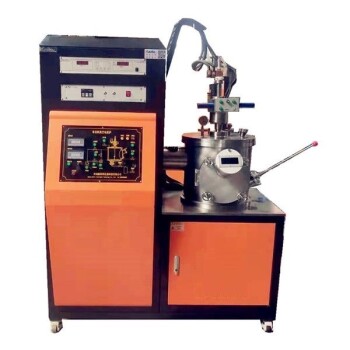
Induction coils in CVD systems rely on water-cooled copper tubes to solve two competing engineering challenges: maximizing energy efficiency and preventing structural failure. Copper is chosen for its superior electrical conductivity, which ensures efficient electromagnetic induction, while the hollow tubular design allows cooling water to circulate internally, actively removing heat to prevent the coil from melting.
High-current processes generate unavoidable "Joule heat" within the coil itself. The design solves this by pairing a highly conductive material (copper) to minimize losses with an active cooling mechanism (water) to manage the thermal load.
The Role of Material Selection
Maximizing Electrical Conductivity
Copper is the standard material for induction coils because it possesses excellent electrical conductivity.
High conductivity minimizes resistive energy loss as electricity flows through the coil.
This efficiency is crucial for generating the strong electromagnetic fields required for the induction heating process.
Minimizing Resistive Losses
When a material resists the flow of electricity, that energy is wasted as heat.
By using copper, the system reduces this "wasted" energy, directing more power toward heating the target material rather than the coil itself.
Managing Thermal Loads
The Problem of Joule Heating
Despite copper's efficiency, the high currents required for Chemical Vapor Deposition (CVD) inevitably generate internal heat.
This phenomenon, known as the Joule effect, causes the coil temperature to rise rapidly during operation.
Without a dissipation mechanism, this heat poses a severe risk to the equipment.
Preventing Structural Failure
The most immediate danger of Joule heating is the melting of the coil.
CVD systems operate under high-power conditions that can easily push copper past its thermal limits.
Active cooling is not optional; it is a safety requirement to maintain the stability of the induction process.
The Engineering Solution
Internal Water Circulation
To manage the heat, induction coils are manufactured as hollow tubes rather than solid bars.
This geometry allows cooling water to circulate continuously through the interior of the copper coil.
Active Heat Dissipation
As water flows through the tube, it absorbs the thermal energy generated by the current.
This effectively dissipates the Joule heat, keeping the copper well below its melting point.
This mechanism ensures the coil remains physically stable even during high-temperature operations.
Understanding the Trade-offs
Complexity vs. Capability
While water-cooled tubes enable high-power operations, they introduce mechanical complexity.
The system requires reliable plumbing, pumps, and seals to ensure water flows constantly without leaking.
Maintenance Implications
The internal waterways must remain unobstructed to function correctly.
Blockages or mineral buildup inside the copper tube can reduce cooling efficiency, leading to localized "hot spots" and potential coil failure.
Making the Right Choice for Your Goal
Balancing electrical efficiency with thermal management is the key to a reliable CVD system.
- If your primary focus is process efficiency: Prioritize high-purity copper construction to minimize resistive losses and maximize energy transfer to the workload.
- If your primary focus is equipment longevity: Ensure your cooling system is rated for the maximum thermal load and monitor flow rates to prevent overheating.
Effective induction heating requires not just generating heat, but controlling where it goes.
Summary Table:
| Component | Material/Design Feature | Primary Benefit |
|---|---|---|
| Coil Material | High-Purity Copper | Maximizes electrical conductivity and reduces resistive energy loss. |
| Physical Shape | Hollow Tubular Design | Enables internal fluid circulation for active thermal management. |
| Cooling Medium | Circulating Water | Effectively dissipates Joule heat to prevent coil melting. |
| System Goal | Electromagnetic Induction | Efficiently transfers energy to the workload for CVD processes. |
Optimize Your CVD Process with KINTEK’s Engineering Excellence
Don't let thermal instability compromise your research or production. KINTEK specializes in advanced laboratory solutions, providing high-performance CVD and PECVD systems equipped with precision-engineered induction heating components. Our copper-coil technology ensures maximum energy efficiency and equipment longevity for the most demanding high-temperature applications.
Whether you need robust high-temperature furnaces, specialized vacuum systems, or precision cooling solutions (ULT freezers and cold traps), KINTEK delivers the reliability your lab deserves. Our team is ready to support your success with high-quality consumables like PTFE products, ceramics, and crucibles.
Ready to upgrade your thermal processing? Contact KINTEK today for a customized solution!
References
- Saphina Biira. Design and fabrication of a chemical vapour deposition system with special reference to ZrC layer growth characteristics. DOI: 10.17159/2411-9717/2017/v117n10a2
This article is also based on technical information from Kintek Solution Knowledge Base .
Related Products
- Multi Heating Zones CVD Tube Furnace Machine Chemical Vapor Deposition Chamber System Equipment
- CVD Diamond for Thermal Management Applications
- Customer Made Versatile CVD Tube Furnace Chemical Vapor Deposition Chamber System Equipment
- HFCVD Machine System Equipment for Drawing Die Nano-Diamond Coating
- Cylindrical Lab Electric Heating Press Mold for Laboratory Applications
People Also Ask
- What is the function of a tube furnace in CVD SiC synthesis? Achieving Ultra-Pure Silicon Carbide Powders
- What is a CVD furnace? The Ultimate Guide to Precision Thin-Film Coating
- What is a CVD tube furnace? A Complete Guide to Thin-Film Deposition
- What advantages do CVD furnaces offer for Wf/W composites? Preserving Fiber Ductility and Interface Integrity
- What is the function of a high-temperature CVD tube furnace in 3D graphene foam prep? Master 3D Nanomaterial Growth