In principle, you control the temperature of a resistance by controlling the electrical power it dissipates as heat. This is achieved through three primary methods: varying the voltage supplied to it, changing its effective resistance, or rapidly switching the power on and off to control the average energy delivered over time. The choice of method depends entirely on the requirements of your application, from simple heat limitation to precise temperature regulation.
The temperature of a resistor is a direct result of the power it converts into heat. Therefore, to control its temperature, you must fundamentally control the electrical power it dissipates, governed by the principles of Joule heating.
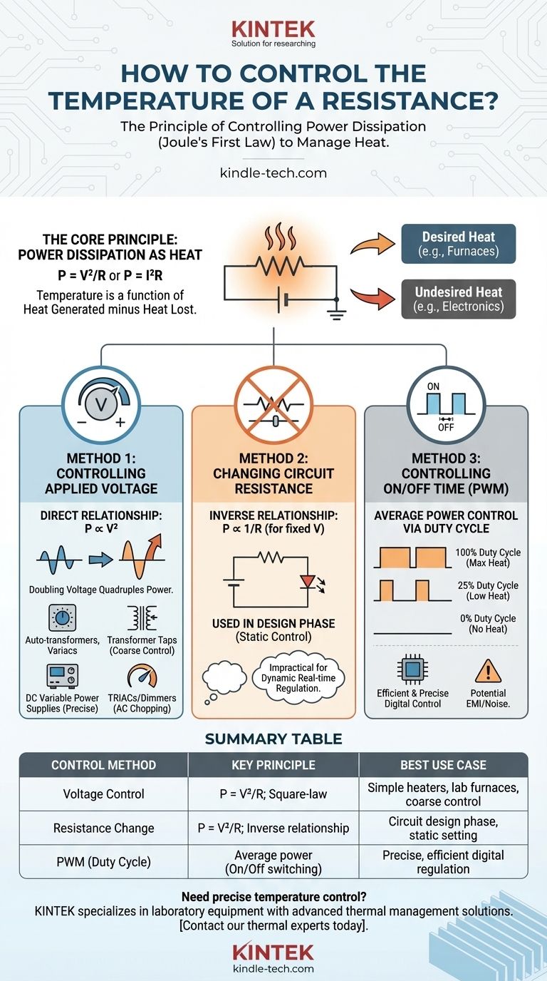
The Core Principle: Power Dissipation as Heat
Joule's First Law
At its core, the temperature of a resistive element is a function of the heat it generates minus the heat it loses to its environment. The heat generated is a direct result of power dissipation, described by Joule's First Law.
The power (P) dissipated as heat can be calculated using two key formulas: P = V²/R (Power equals voltage squared divided by resistance) or P = I²R (Power equals current squared times resistance). To control temperature, you must manipulate one of these variables: voltage (V), current (I), or resistance (R).
Desired vs. Undesired Heat
This control is critical in two opposing scenarios. In applications like furnaces or heaters, heat is the desired output. In most electronic circuits, however, heat is an undesirable byproduct that must be managed to prevent component damage.
Method 1: Controlling the Applied Voltage
The Direct Relationship
According to the formula P = V²/R, power is proportional to the square of the voltage. This means even small changes in voltage have a significant impact on heat output, making it a very effective control method. Doubling the voltage, for instance, quadruples the power dissipated.
Practical Implementations
This can be done using several devices, each suited for different scales.
- Auto-transformers and Variable Transformers: These allow for manual, continuous adjustment of AC voltage and are common in lab settings and simple industrial controls.
- Transformer Taps: Large furnaces often use transformers with multiple output windings (taps) to switch between different fixed voltage levels for coarse temperature control.
- Variable Voltage Power Supplies: For DC circuits, a laboratory-style power supply provides precise voltage control.
- TRIACs/Dimmers: For AC resistive loads like simple heaters or incandescent bulbs, a TRIAC-based circuit (like a common light dimmer) controls temperature by chopping the AC waveform, effectively reducing the RMS voltage.
Method 2: Changing the Circuit Resistance
The Inverse Relationship
Looking at P = V²/R, for a fixed voltage source, power is inversely proportional to resistance. Increasing the resistance decreases the current flow, which in turn reduces the power dissipated as heat.
When This Method Is Used
This method is almost exclusively used during the design phase of a circuit rather than for real-time temperature regulation. It is impractical to dynamically change a physical resistor value.
For example, when designing a simple LED circuit, you choose a specific resistor value to limit the current and prevent the LED from overheating. You are controlling its operating temperature by fundamentally limiting the power it can draw.
Method 3: Controlling the On/Off Time (Duty Cycle)
The Concept of Averaging Power
This modern digital technique does not change the voltage or resistance. Instead, it switches the full power to the resistor on and off very quickly, hundreds or thousands of times per second. By varying the ratio of "on" time to "off" time, you control the average power delivered.
Pulse-Width Modulation (PWM)
This method is most commonly implemented using Pulse-Width Modulation (PWM). The ratio of on-time to the total period of a cycle is called the duty cycle.
- A 100% duty cycle means the power is always on (maximum heat).
- A 25% duty cycle means the power is on for only a quarter of the time (low heat).
- A 0% duty cycle means the power is always off.
Why PWM is So Common
PWM is extremely efficient and precise. The switching transistor used to control the power is either fully on (very low resistance) or fully off (nearly infinite resistance), meaning it dissipates very little heat itself. This makes it ideal for battery-powered or high-power applications where energy efficiency is critical.
Understanding the Trade-offs
Voltage Control (Linear)
This method is straightforward but can be inefficient. A linear regulator, for instance, controls voltage by burning excess power as its own heat, which is wasteful. Transformers are more efficient for AC but are often bulky and expensive.
Resistance Control (Design)
This approach is simple and reliable for static applications where you need to set a fixed operating temperature or limit. It is completely impractical for applications requiring dynamic temperature changes.
Duty Cycle Control (PWM)
PWM offers the best combination of efficiency and precision, making it the standard for modern digital control. However, the high-frequency switching can introduce electromagnetic interference (EMI) or "electrical noise" into a system, which may require additional filtering in sensitive applications.
Making the Right Choice for Your Goal
Selecting the correct method depends on your specific objective.
- If your primary focus is designing a simple, high-power heater: Start with voltage control using a tapped transformer for coarse steps and consider adding PWM for fine, efficient regulation.
- If your primary focus is limiting heat in a standard electronic circuit: Concentrate on resistance control during the design phase by selecting the proper resistor values to limit current to a safe level.
- If your primary focus is achieving precise, efficient temperature regulation: Use Pulse-Width Modulation (PWM) controlled by a microcontroller, as it provides the most accurate and energy-efficient solution.
By matching the control strategy to your application's needs, you can reliably and safely manage the thermal behavior of any resistive element.
Summary Table:
| Control Method | Key Principle | Best Use Case |
|---|---|---|
| Voltage Control | P = V²/R; Square-law relationship | Simple heaters, lab furnaces, coarse control |
| Resistance Change | P = V²/R; Inverse relationship | Circuit design phase, static temperature setting |
| PWM (Duty Cycle) | Average power control via on/off switching | Precise, efficient digital temperature regulation |
Need precise temperature control for your lab equipment? KINTEK specializes in laboratory equipment and consumables with advanced thermal management solutions. Whether you're designing a custom heating system or need reliable components for precise temperature regulation, our expertise ensures optimal performance and efficiency. Contact our thermal solutions experts today to discuss how we can enhance your laboratory's capabilities!
Visual Guide
Related Products
- High Temperature Resistant Optical Quartz Glass Sheet
- Laboratory Small Constant Temperature Heated Magnetic Stirrer Heater and Stirrer
- Double-Layer Water Bath Electrolytic Electrochemical Cell
- Oxygen Probe to Measure Temperature and Active Oxygen Content in Molten Steel
People Also Ask
- What is the high temperature variety of quartz? Unlock the Secrets of Beta-Quartz & Fused Quartz
- What is high temperature quartz? A Guide to Unmatched Thermal Stability & Purity
- What is the high temperature of quartz? Key Thresholds for Crystalline vs. Fused Silica
- What temperature does quartz glass melt at? Understanding Its Softening Point and Practical Limits
- Can quartz glass be heated? Mastering High-Temperature Applications with Quartz