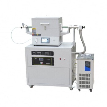
A typical Chemical Vapor Deposition (CVD) equipment setup is an integrated assembly of seven critical subsystems designed to control gas flow, pressure, and thermal energy.
These components are the gas delivery system, reaction chamber (reactor), loading/unloading system, energy source, vacuum system, process automatic control system, and exhaust gas treatment system.
Core Takeaway A CVD system functions as a precisely controlled environment where volatile precursors are introduced, chemically reacted via an energy source, and deposited as a solid film. The equipment's primary goal is to maintain specific conditions—mass flow, temperature, and pressure—to ensure high-purity, uniform coatings.
The Anatomy of a CVD System
To understand how CVD achieves "bottom-up" film growth, we must examine the specific function of each component within the workflow.
1. Gas Delivery System
This system is the entry point for the process. It manages the introduction of volatile compounds (reactants) and carrier gases into the system.
Its primary role is to precisely control the mass flow of each component. This ensures the correct stoichiometry (chemical balance) reaches the reaction chamber.
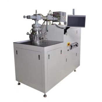
2. The Reaction Chamber (Reactor)
The reactor is the vessel where the chemical transformation occurs. It provides a controlled environment where combined gases contact the heated substrate.
Inside this chamber, the gas phase reactants undergo thermal decomposition or chemical reaction. This results in the nucleation and growth of the solid material film on the substrate surface.
3. Energy Source
External energy is required to drive the chemical reaction. While this is typically a heat source aimed at the substrate or chamber walls, it can also involve plasma or light radiation.
This component is critical because film growth usually requires temperatures sufficient to decompose the precursor vapor, often differentiating CVD from other deposition methods.
4. Vacuum System
Most CVD processes require specific pressure environments, ranging from normal pressure to low vacuum.
The vacuum system regulates the background pressure within the chamber. This control is vital for managing the mean free path of gas molecules and ensuring uniform diffusion across the substrate.
5. Exhaust Gas Treatment System
Chemical reactions in CVD inevitably produce byproducts. This system is responsible for the safe removal of excess gaseous waste and nonvolatile reaction products.
It pumps these waste gases out of the chamber and treats them to meet environmental and safety standards before venting.
6. Loading and Unloading System
This mechanism handles the physical movement of substrates into and out of the reaction chamber.
It ensures that the placement of the substrate—whether a simple wafer or a complex shape—is consistent, which is crucial for repeatability.
7. Process Automatic Control System
Modern CVD requires precise synchronization of all variables. This system monitors and adjusts parameters such as temperature, pressure, and gas flow rates in real-time.
It ensures the process remains stable and reproducible, minimizing operator error.
Understanding the Trade-offs
While CVD equipment is generally considered simple to operate and maintain, there are physical limitations inherent to the hardware setup.
Thermal Constraints
The most significant limitation is the high reaction temperature, traditionally falling between 850°C and 1100°C.
Standard heating components in a CVD setup may generate temperatures that exceed the melting point or thermal tolerance of many substrate materials. To mitigate this, specialized setups using plasma or laser-assisted energy sources may be required to lower the necessary process temperature.
Making the Right Choice for Your Goal
Selecting the right CVD configuration depends heavily on the geometry of your workpiece and the thermal sensitivity of your material.
- If your primary focus is complex geometries: Rely on the CVD's excellent throwing power and pressure control to coat deep holes and intricate shapes uniformly.
- If your primary focus is delicate substrates: Investigate plasma-enhanced or laser-assisted energy sources to achieve high-quality films without subjecting the substrate to extreme thermal stress.
- If your primary focus is purity and structure: Prioritize the vacuum and gas delivery systems to ensure strict control over contamination and grain size.
Success in Chemical Vapor Deposition is ultimately defined by how effectively your equipment enables you to manipulate the reaction environment at the atomic level.
Summary Table:
| Component | Primary Function | Key Role in Film Growth |
|---|---|---|
| Gas Delivery System | Flow & stoichiometry control | Precise management of precursors and carrier gases |
| Reaction Chamber | Controlled environment | Site for chemical reaction and film nucleation |
| Energy Source | Thermal/Plasma energy | Provides activation energy to decompose precursors |
| Vacuum System | Pressure regulation | Controls gas mean free path and ensures uniformity |
| Exhaust System | Waste removal | Safely treats and vents gaseous reaction byproducts |
| Automatic Control | Process synchronization | Real-time monitoring of temperature, pressure, and flow |
| Loading System | Substrate handling | Ensures consistent placement and process repeatability |
Elevate Your Material Research with KINTEK Precision
Unlock the full potential of your thin-film applications with KINTEK’s high-performance CVD and PECVD systems. Whether you are working on complex geometries or delicate substrates, our specialized laboratory equipment—ranging from advanced tube and vacuum furnaces to precision gas delivery solutions—is designed to provide absolute control over your reaction environment.
Why Choose KINTEK?
- Comprehensive Range: From MPCVD and rotary furnaces to high-temperature reactors and crushing systems.
- Unmatched Precision: Real-time automatic control systems for repeatable, high-purity results.
- Expert Support: Tailored solutions for battery research, ceramics, and advanced material science.
Ready to optimize your deposition process? Contact KINTEK today for a customized consultation!
Related Products
- Chemical Vapor Deposition CVD Equipment System Chamber Slide PECVD Tube Furnace with Liquid Gasifier PECVD Machine
- Microwave Plasma Chemical Vapor Deposition MPCVD Machine System Reactor for Lab and Diamond Growth
- 915MHz MPCVD Diamond Machine Microwave Plasma Chemical Vapor Deposition System Reactor
- Customer Made Versatile CVD Tube Furnace Chemical Vapor Deposition Chamber System Equipment
- HFCVD Machine System Equipment for Drawing Die Nano-Diamond Coating
People Also Ask
- What types of substrates are used in CVD to facilitate graphene films? Optimize Graphene Growth with the Right Catalyst
- What are the core advantages of PE-CVD in OLED encapsulation? Protect Sensitive Layers with Low-Temp Film Deposition
- What are the advantages of chemical vapor deposition? Achieve Superior Thin Films for Your Lab
- What is the chemical vapor deposition growth process? Build Superior Thin Films from the Atom Up
- What is plasma enhanced chemical vapor deposition PECVD equipment? A Guide to Low-Temperature Thin Film Deposition