To calculate induction heating power, you must first determine the thermal energy required to heat your material to the target temperature within a specific time, and then adjust this figure to account for heat losses and the electrical efficiency of your induction system. The core calculation involves the material's mass, its specific heat capacity, and the desired temperature change.
The crucial insight is that the power you calculate for the material itself is only a baseline. The actual power your system must provide will always be higher, as you must compensate for energy lost to the surrounding environment and inefficiencies within the power supply and induction coil.
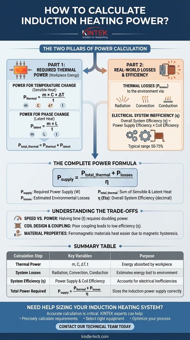
The Two Pillars of Power Calculation
To arrive at a realistic power requirement, we must separate the calculation into two distinct parts: the energy the workpiece needs to absorb and the additional energy required to overcome system losses.
Part 1: Calculating Required Thermal Power
This is the net power that must be delivered to the workpiece to achieve the desired result. It is the sum of the power needed for temperature change and, if applicable, for phase change.
Power for Temperature Change (Sensible Heat)
This calculation determines the power needed to raise the temperature of a solid or liquid material without changing its state (e.g., from solid to liquid).
The formula is: P_thermal = (m × C × ΔT) / t
Where:
- P_thermal is the power required in Watts (W).
- m is the mass of the workpiece in kilograms (kg).
- C is the specific heat capacity of the material in Joules per kilogram per degree Celsius (J/kg°C).
- ΔT (Delta T) is the change in temperature in degrees Celsius (°C).
- t is the required heating time in seconds (s).
Power for Phase Change (Latent Heat)
If your process involves melting or boiling (evaporation), you must calculate the additional energy required for this phase transition. This occurs at a constant temperature.
The formula is: P_latent = (m × L) / t
Where:
- L is the specific latent heat of the material (e.g., latent heat of fusion for melting).
- The other variables are the same as above.
Your total thermal power is the sum of these two: P_total_thermal = P_thermal + P_latent.
Part 2: Accounting for Real-World Losses
An induction system is not 100% efficient. The power drawn from the electrical mains will be significantly higher than the thermal power absorbed by the workpiece.
Thermal Losses to the Environment
The workpiece does not exist in a vacuum. As it heats up, it will continuously lose energy to its surroundings through several mechanisms.
- Radiation: Heat radiates away, especially at high temperatures.
- Convection: Air currents carry heat away from the surface.
- Conduction: Heat is lost to any fixtures or supports in direct contact with the workpiece.
These losses, collectively called P_losses, increase as the workpiece gets hotter and must be added to your thermal power calculation.
Electrical System Inefficiency
The process of converting mains electricity into a high-frequency magnetic field is not perfectly efficient.
The overall system efficiency (η) is a product of the power supply efficiency and the coil efficiency. A well-designed system might have an overall efficiency of 50-75%, but this can be much lower if the coil is poorly matched to the workpiece.
The Complete Power Formula
To find the actual power your induction heater must draw from the mains, you must combine all these factors.
Putting It All Together
The final calculation provides the most accurate estimate for sizing your power supply.
P_supply = (P_total_thermal + P_losses) / η
Where:
- P_supply is the power required from the power supply in Watts.
- P_total_thermal is the sum of power for temperature and phase change.
- P_losses is the estimated power lost to the environment.
- η (Eta) is the overall system efficiency (as a decimal, e.g., 0.6 for 60%).
Understanding the Trade-offs
Simply applying the formula is not enough; you must understand the key variables that create critical trade-offs in any induction heating application.
Speed vs. Power
The formulas clearly show that heating time (t) is in the denominator. Halving the heating time requires doubling the power, assuming all else is equal. This relationship is a primary driver of equipment cost and size.
Coil Design and Coupling
The efficiency of energy transfer depends heavily on the coupling—the proximity and geometric relationship between the coil and the workpiece. A loose-fitting coil with large gaps will have poor coupling, leading to low efficiency (a low η) and wasted energy.
Material Properties
The material itself dictates how effectively it can be heated. Ferromagnetic materials like steel also generate heat through magnetic hysteresis losses below their Curie temperature, making them easier to heat than non-magnetic materials like aluminum or copper, which rely solely on eddy currents.
Sizing Your Induction System Correctly
Use these principles to select the right approach for your specific goal.
- If your primary focus is a rough initial estimate: Calculate the basic thermal power
(m × C × ΔT) / tand then double it as a conservative starting point to account for unknown losses and inefficiencies. - If your primary focus is designing a new production system: You must perform detailed calculations for thermal losses and use an estimated efficiency (e.g., 60%) to size your power supply, leaving a safety margin.
- If your primary focus is process optimization: Concentrate on improving coil coupling and insulating the workpiece to minimize
P_lossesand maximizeη, allowing you to achieve faster cycle times with your existing power supply.
Ultimately, a precise power calculation empowers you to make informed engineering decisions for a more efficient and cost-effective heating process.
Summary Table:
| Calculation Step | Key Variables | Purpose |
|---|---|---|
| Thermal Power | Mass (m), Specific Heat (C), Temp Change (ΔT), Time (t) | Determines energy absorbed by the workpiece. |
| System Losses | Radiation, Convection, Conduction | Estimates energy lost to the environment. |
| System Efficiency (η) | Power Supply & Coil Efficiency | Accounts for electrical inefficiencies. |
| Total Power Required | P_supply = (P_thermal + P_losses) / η | Sizes the induction power supply correctly. |
Need help sizing your induction heating system?
Accurate power calculation is critical for process efficiency and equipment longevity. The experts at KINTEK specialize in lab equipment and consumables, including induction heating solutions. We can help you:
- Precisely calculate your power requirements to avoid under or over-sizing your system.
- Select the right equipment for your specific material and application.
- Optimize your process for maximum energy efficiency and throughput.
Don't leave your project to chance. Contact our technical team today for a personalized consultation and ensure your induction heating process is a success.
Visual Guide