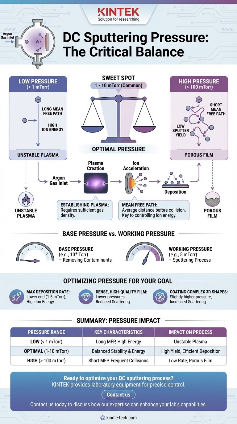
The required pressure for DC sputtering is a critical balancing act. It typically operates within a working pressure range of 1 to 100 millitorr (mTorr), with a common sweet spot between 1 and 10 mTorr. This pressure is established using an inert process gas, most commonly Argon, after the chamber has been evacuated to a much lower base pressure.
The central challenge in DC sputtering is setting a pressure that is high enough to sustain a stable plasma discharge, yet low enough to ensure ions have a long "mean free path" to strike the target with sufficient energy for efficient material ejection.
The Role of Pressure in the Sputtering Process
To understand why a specific pressure range is used, we must look at the two competing requirements of the DC sputtering process: creating a plasma and accelerating ions effectively.
Establishing the Plasma
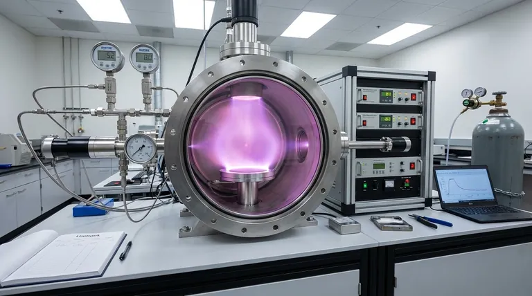
The sputtering process begins by introducing a low-pressure inert gas (like Argon) into a vacuum chamber and applying a high voltage. This voltage ionizes the gas atoms, creating a sustained glow discharge, or plasma. The pressure must be high enough to provide a sufficient density of gas atoms to reliably ignite and maintain this plasma.
Defining the Mean Free Path
Mean free path is the average distance a particle—in this case, an Argon ion—travels before colliding with another particle. This concept is the single most important factor controlled by pressure.
A lower pressure results in fewer gas atoms in the chamber, leading to a longer mean free path. Conversely, a higher pressure means more gas atoms and a shorter mean free path.
Impact on Ion Energy
Ions are accelerated by the electric field toward the target material. To achieve a high sputtering rate, these ions must strike the target with maximum kinetic energy.
A long mean free path (lower pressure) allows ions to travel uninterrupted for greater distances, gaining more energy from the electric field before impact. This results in more forceful collisions and a higher yield of sputtered atoms from the target.
Understanding the Trade-offs of Sputtering Pressure
The optimal pressure for your process is a trade-off between plasma stability, deposition rate, and final film quality. Choosing a pressure outside the ideal range can lead to significant problems.
The Problem with High Pressure (>100 mTorr)
When the pressure is too high, the mean free path becomes very short. Ions constantly collide with neutral gas atoms, preventing them from gaining significant energy before striking the target.
This leads to a low sputter yield and a slow deposition rate. Furthermore, the sputtered atoms themselves will collide with gas atoms on their way to the substrate, causing them to lose energy and scatter, which can result in a porous, low-density film.
The Challenge of Low Pressure (<1 mTorr)
When the pressure is too low, the mean free path is very long, which is ideal for ion acceleration. However, the density of gas atoms becomes insufficient to sustain a stable plasma discharge.
At these low pressures, the plasma can become unstable or extinguish entirely, making the process unreliable or impossible to run.
Base Pressure vs. Working Pressure: A Critical Distinction
It is essential to distinguish between the initial vacuum level and the final process pressure.
Base pressure is the deep vacuum achieved before introducing the process gas (e.g., 10⁻⁶ Torr). Its purpose is to remove contaminants like oxygen and water vapor that would otherwise get incorporated into your film and compromise its purity and properties.
Working pressure (or process pressure) is the higher pressure (e.g., 5 mTorr) established by backfilling the chamber with a controlled flow of inert gas after achieving a satisfactory base pressure. This is the pressure at which the sputtering actually occurs.
Optimizing Pressure for Your Goal
The ideal pressure setting depends entirely on the desired outcome for your thin film.
- If your primary focus is maximizing deposition rate: Aim for the lower end of the stable pressure range (e.g., 1-5 mTorr) to maximize ion energy, but be mindful of plasma stability.
- If your primary focus is creating a dense, high-quality film: Lower pressures are generally better, as they reduce gas-phase scattering and lead to more energetic sputtered atoms arriving at the substrate.
- If your primary focus is coating a complex, 3D shape: A slightly higher pressure may be beneficial, as increased scattering can help coat non-line-of-sight surfaces more uniformly.
Ultimately, treating pressure as a key tuning parameter is essential for achieving consistent and high-quality results in your thin-film deposition process.
Summary Table:
| Pressure Range | Key Characteristics | Impact on Process |
|---|---|---|
| Low (< 1 mTorr) | Long mean free path, high ion energy | Unstable plasma, difficult to sustain discharge |
| Optimal (1-10 mTorr) | Balanced plasma stability and ion energy | High sputter yield, efficient deposition |
| High (> 100 mTorr) | Short mean free path, frequent collisions | Low deposition rate, porous film quality |
Ready to optimize your DC sputtering process? The precise control of pressure parameters is crucial for achieving consistent, high-quality thin films. At KINTEK, we specialize in providing laboratory equipment and consumables that deliver the reliability and precision your research demands.
Our sputtering systems are designed to help you master the delicate balance of pressure, plasma stability, and deposition quality. Whether you're working on advanced materials research or developing next-generation coatings, KINTEK has the solutions to support your success.
Contact us today to discuss how our expertise can enhance your lab's capabilities. Let's work together to achieve your thin-film deposition goals. Get in touch with our experts now!
Visual Guide
Related Products
- Spark Plasma Sintering Furnace SPS Furnace
- Vacuum Induction Melting Spinning System Arc Melting Furnace
- Circulating Water Vacuum Pump for Laboratory and Industrial Use
People Also Ask
- What technical advantages does a Spark Plasma Sintering (SPS) furnace offer for LZP ceramics? Enhance Ionic Conductivity
- What are the fundamentals of spark plasma sintering process? Unlock Rapid, High-Performance Material Consolidation
- Why are Spark Plasma Sintering (SPS) furnaces or hot presses utilized in the preparation of Li3PS4 solid electrolytes?
- What is the theory of spark plasma sintering? A Guide to Rapid, Low-Temperature Densification
- What is the pressure for spark plasma sintering? A Guide to Optimizing SPS Parameters