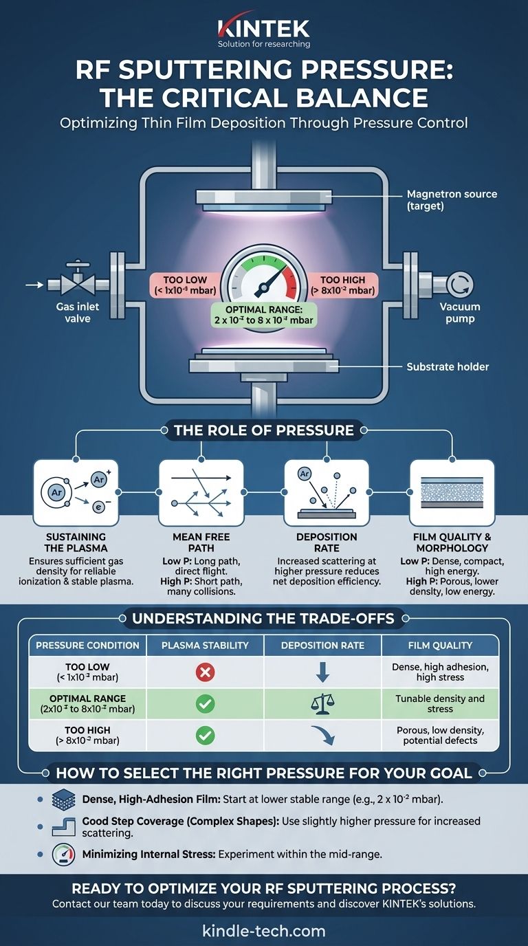
In RF magnetron sputtering, the typical operating pressure is set within a narrow vacuum range, generally between 2 x 10⁻² and 8 x 10⁻² millibar (mbar). This specific working pressure is not arbitrary; it is a critical parameter required to both ignite and sustain a stable plasma while directly influencing the quality and characteristics of the deposited thin film.
The core challenge in RF sputtering is finding the optimal pressure that balances two competing needs: it must be high enough to provide sufficient gas atoms to maintain a stable plasma, yet low enough to ensure sputtered material can travel to the substrate efficiently and with enough energy to form a high-quality film.
The Role of Pressure in the Sputtering Process
Choosing the right pressure is fundamental to controlling the deposition. It directly dictates the environment between the material source (the target) and your substrate.
Sustaining the Plasma
The sputtering process begins by introducing an inert gas, typically Argon, into the vacuum chamber. An RF voltage is applied, which ionizes these gas atoms, creating a plasma.
The working pressure is a measure of the density of these gas atoms. If the pressure is too low, there won't be enough atoms to reliably ionize, and the plasma will be unstable or extinguish completely.
Mean Free Path
Mean free path is the average distance a particle travels before it collides with another particle. This concept is central to understanding the effect of pressure.
At lower pressures, the mean free path is long. Sputtered atoms ejected from the target travel in a more direct, "line-of-sight" path to the substrate with minimal collisions.
At higher pressures, the mean free path is short. Sputtered atoms are much more likely to collide with gas atoms, scattering them and reducing their energy before they reach the substrate.
Deposition Rate
Pressure has a direct impact on the efficiency of the deposition. While higher RF power increases the sputtering rate from the target, higher pressure works against it.
Increased scattering at higher pressures means fewer sputtered atoms reach the substrate, which effectively lowers the net deposition rate.
Film Quality and Morphology
The energy and arrival angle of sputtered atoms determine the final structure of the film.
A lower pressure process results in atoms arriving with higher kinetic energy. This generally produces denser, more compact films with better adhesion, but can sometimes increase compressive stress.
A higher pressure process results in atoms arriving with lower energy from a wider range of angles due to scattering. This often leads to more porous films with lower density and potentially different crystalline structures.
Understanding the Trade-offs
There is no single "best" pressure. The optimal setting is always a trade-off based on the goals of your specific application.
The Problem with Pressure That Is Too Low
Operating below the stable range (e.g., < 1 x 10⁻³ mbar for many systems) makes it difficult to ignite and sustain the plasma. The process becomes unreliable and difficult to control.
The Problem with Pressure That Is Too High
Excessively high pressure causes significant gas scattering, which dramatically reduces the deposition rate. It can also lead to gas atoms becoming embedded in the growing film, creating impurities and defects that compromise its performance.
Balancing Competing Factors
The ideal pressure is a balance. You must find the sweet spot that provides a stable plasma, an acceptable deposition rate, and the specific film characteristics—such as density, stress, and electrical resistivity—that your application requires.
How to Select the Right Pressure for Your Goal
The ideal pressure is not a single number but depends entirely on the desired outcome for your thin film.
- If your primary focus is a dense, high-adhesion film: Start at the lower end of the stable pressure range (e.g., 2 x 10⁻² mbar) to maximize the energy of atoms arriving at the substrate.
- If your primary focus is coating a complex shape (good step coverage): A slightly higher pressure can be beneficial, as increased scattering helps atoms deposit on non-line-of-sight surfaces.
- If your primary focus is minimizing internal film stress: You may need to experiment within the mid-range of pressures, as this is often a complex function of both pressure and atom energy.
Ultimately, controlling sputtering pressure is your primary tool for fine-tuning the balance between deposition efficiency and the final physical properties of your material.
Summary Table:
| Pressure Condition | Plasma Stability | Deposition Rate | Film Quality |
|---|---|---|---|
| Too Low (< 1x10⁻³ mbar) | Unstable, difficult to ignite | Low | Dense, high adhesion, high stress |
| Optimal Range (2x10⁻² to 8x10⁻² mbar) | Stable | Balanced | Tunable density and stress |
| Too High (> 8x10⁻² mbar) | Stable but inefficient | Very low | Porous, low density, potential defects |
Ready to Optimize Your RF Sputtering Process?
Achieving the perfect pressure balance is key to producing high-quality thin films. At KINTEK, we specialize in providing precision lab equipment and consumables tailored to your laboratory's unique needs. Our experts can help you select the right sputtering system and parameters to ensure stable plasma, optimal deposition rates, and superior film characteristics for your specific application.
Let us help you enhance your research and production outcomes. Contact our team today to discuss your RF sputtering requirements and discover how KINTEK's solutions can drive your success.
Visual Guide
Related Products
- RF PECVD System Radio Frequency Plasma-Enhanced Chemical Vapor Deposition RF PECVD
- Spark Plasma Sintering Furnace SPS Furnace
- Horizontal High Temperature Graphite Vacuum Graphitization Furnace
People Also Ask
- What is the role of RF-PECVD in VFG preparation? Mastering Vertical Growth and Surface Functionality
- What is plasma enhanced chemical Vapour deposition process used for fabrication of? A Guide to Low-Temperature Thin Films
- Why is a Matching Network Indispensable in RF-PECVD for Siloxane Films? Ensure Stable Plasma and Uniform Deposition
- What is plasma enhanced chemical vapour deposition PECVD used for? Enable Low-Temp Thin Films for Electronics & Solar
- What is plasma CVD? Unlock Low-Temperature Thin Film Deposition for Sensitive Materials


